Sir Andrew Ceeeeeeeeeeeeee . . . . . . .
I started on a write up for analysis of your unit . . . . . but don't have time to complete now, plus I need some visual inspection, in your hand, for confirmations .
Firstly, on that somewhat shaky pie in the sky info received on your transistor types . . . . . . . . now a RotoMola semiconductor plant worker in Arizona in 1987 times would have known that the color stripe codes are used to keep up with the identity of that transistor, after it has been encapsulated within its TO-92 potted housing, but has not yet reached the symbolization area.
Then there they will mark it with that cryptic " 8467 " . . . . no sense . . . . gibberish . . . house number * . . . . .that GM requested for it, along with their own addition, time sensitive, second lines 747. Which really means a factory line date code of 747. . . . . . .which relates to 1987 and the 47th week of that year . . . . . . . . thusly . . . . .747.
( * That stops in plant pilferage / shrinkage , unless that * / to real world is known.)
A far cry from your transistors being that guessed at / suggested BC747.
Just look . . . . . their lead pin outs don't even agree with yours plus in my looking at your board and reading its foil trace "schematic" is clearly defining them as being NPN's.
They label . . . . . as a reed switch . . . . . . what I have called . . . for 75 yrs . . . a leaf switch, and it is being activated with the rotating 270 degree blue wheel at one extreme end of its travel limit..
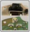
I am not seeing a pic that shows that switch's contacts, but in using post #11's pic, which now is having no BLUE wheel to be able to engage into it.
Question, are those 2 contacts NOW being firmly closed . . . . . which I suspect.
Should the unit then be assembled, such that the BLUE wheel will engage , I'm suspecting the leafs folded over protrusion engages with BLUE wheel at its travel limit, to let turned off wipers, keep running until wipers again reach extreme bottom arc . . . . . . blade park position.
WHATYOUSEEANDWHATYOUTHINKTHATYOUSEEARENOTREALLYBEINGWHATYOUACTUALLYSEE . . . . .
specifically . . . .

Those 3 micro brass rivets are related to mechanically holding the top BLACK connections cover in place.
The connectors large central blade connector and its two minor side connectors are made to be akin to a
spade connector

and you can see the two end "barbs" that pass thru holes in the PCB for electrical connectivity.
ON THAT CONNECTOR . . . .
You can figure out . . . or MAYBE some can figure out . . . . that the LARGE center blade makes two HARD 90 degree bends to then come out up at the top YELLOW bar mark up. That whole foil is being a common ground buss.
I also think that the two side connections go to a wiring harness, to end at a switch that selects between two delay wiper options . . . . . . . am I right . . .Andrewski . . . on there only being
TWO delay wiper operational options ?
WORK IN PROGRESS . . . . . PRELIMINARY TECHNO-MECHANO REFERENCING . . . . .

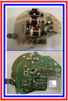
I see this units concept of design as being a relay driver that has an option of change between 2 stored E caps state of charge.
Thereby the base voltage is bleeding down with time, by virtue of having a high value bleeder resistor, shunted across their capacitance.
RED Q2 is a relay driver transistor.
Its collector goes to RED flag relay coil connection.
(The other relays, driver transistor is the YELLOW Q4 )
That other relay coil connection that goes to 12 VDC power is the YELLOW flag relay coil connection.
Inspect the board and confirm for me, is that correct ?
Also confirm my assigned VIOLET Q4 (YELLOW) collector connection and GREEN 12 VDC supply coming up from D5 diode.
My multiple ( Z) ee markings are tracking the ground path continuity all around the boards foil paths.
Also since OPEN FRAME relays are being used, you can see the relay contacts with one dummy contact that the armature movable contact normally rests against.
When the coil is activated the movable contact moves over to the REAL other contact.
Wel l l l l l l l l l l . . . . . that steel armature framework has two side stud extensions being outside one side that we cannot see so easily by photo.
Those are large ~1/8 inch square steel studs and appear like large versions of the earlier referenced spade stakes.
Confirm those two sets of studs per relay and inspect my two sets of RED and BLUE star assignments and see if I have them/the studs assigned to the proper foil pads . . . thus . . . . . . you are then confirming a 99 87/100 ths degree of my certainty.
Also lets let them designate as BLUE and RED relay differentiation for later referencing.
Considering those associated foil traces . . . . the RED stars have inter connections to a common foil.
HOWEVER the BLUE stars provide a critical connection between two separate foil paths, one coming up from the bottom to a BLUE star , and another foil coming in from the right to the other BLUE star.
Those are two solder connections that need to be positively confirmed, otherwise, top right corner circuitry is left floating.
I also don't like the looks of those D and E pads and their "toilet bowl lime scale deteris" along with the generally eroded divots where the other portions two pressure contacts are to rest into.
Answer the posed queries and don't forget the initial at rest state of the A leaf switch contacts. . . . . . normally open or closed ? ( It engages grounding )
Thaaaaaaaaaaaaaaaaaaaaaasssit . . . . . . .within my available time constraints . . . . .
73's de Edd . . . . .
Some people cause happiness wherever they go . . . . . . . for others . . . . . its being whenever they finally go.
.


