Maker Pro
Maker Pro

Help with figuring out a blown thermistor (?) in a 12v power supply unit (S-360-12)

Discoveryellow

May 23, 2016
7
Joined
May 23, 2016
Messages
7
I have a S-360-12 power supply unit that I got brand new on eBay for a nifty $20. Unfortunately it suddenly stopped working today. I was nearby when I heard a gently but clear "pop" and the LED lights went out.

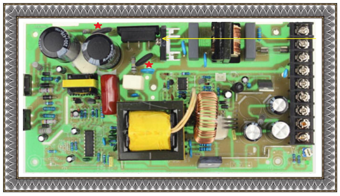
Upon cracking the unit open I found a circular component (see attached photo) boobing around loose inside and a fairly obvious location on the PCB (ever so slightly and barely visibly browned but with solder looking like it had melted) where it came from. As the component was nearly cracked in half the only marking visible were "TC" and a "5" on the line below. Initially I though it was a large high voltage ceramic capacitor. However upon examining a similar lower wattage LED strip power supply unit (still in working order) I found a slightly smaller component labeled "NTC 5D-11" located in the same general area on the PCB next to AC input line.

From half an hour of Web search I am almost confident the blown up part in my S-360-12 LED power supply is a thermistor. But unfortunately I can neither confirm with 100% it is, nor can I know for sure the marking it had. I suspect it was a "5D-15". Can anyone help confirm if (a) it was indeed a thermistor that blew up and (b) that it is a 5D-15?

I am looking for some nomenclature / lists of thermistors to see how they are labeled and organized to understand what the "5D" and "15" stand for? Should I look for a "better" replacement? Also where can I get one in a timely manner? (Usually I get parts from China via eBay, but I tend to plan my projects and needs weeks in advance to allow for shipping times. Local RadioShack is a joke. I live in the nation's capital.)

Also any ideas why would it blow up like this? I have been running a constant 12A load for 16 hour a day for about 5 weeks since I got this power supply. It is rated at 30A so I am certainly not even at 50% of it's power capability.

Thanks for reading and any help will be very much appreciated. The LEDs are part of a living ecosystem so I am a bit pinched with no backup readily available.
 

Attachments

  • IMG_20160522_221309.jpg
    IMG_20160522_221309.jpg
    56.2 KB · Views: 567

(*steve*)

¡sǝpodᴉʇuɐ ǝɥʇ ɹɐǝɥd
Moderator
Jan 21, 2010
25,510
Joined
Jan 21, 2010
Messages
25,510
it could be a negative temperature coefficient resistor.

these are designed to have a relatively high resistance when cold, with that resistance falling as they heat up. They are sometimes used to limit inrush currents.

it is possible that the one you had was poorly chosen or faulty.

The selection of an appropriate device depends on your supply voltage and the normal load.
 

73's de Edd

Aug 21, 2015
3,629
Joined
Aug 21, 2015
Messages
3,629
.


Sir Discoveryellow . . . . . . .

On the unit, see the YELLOW incoming line with your AC line input until it gets to the arrow tip with your AC to DC rectifier and then that is the point where those thermistors come into play.

That DC is to be sent to the left to those two large black UNCHARGED capacitors.
Their required high capacitive values would present such a great loading on that supply that is almost like looking into a short circuit .
The series thermistor is presenting an initial 5 ohms current limiting resistance which will isolate and let the caps initially receive a metered charge.
But simultaneously, their resistance is declining in value and letting the capacitors fully charge up and yet have a minor effect by their being in circuit.

You are correct on your lookup as being the 5D as a 5 ohm cold unit and the second numeral on most manufacturers is relevant to the casing size
Which you are seeing as the 11 versus 15 , you might see how close they come to 11mm or 15 mm measurements if that is being their referencing manner ..

If this was my problem to solve I would install a 60 watt incandescant lamp with interconnect wiring to initially replace the bad thermistor .
Then if you power up and get an initial glow and dimming the unit will probably then justify the thermistors replacement. (Know whut . . . .Spel Chek dussent knows hows to spels "thermistor")

HOWEVER if the lamp GLOWS . . . . you have bad parts that caused that thermistor to BLOW, however I would have expected that far top right glass AC line fuse, to have blown also.

Check it all out . . . . .

Wanna see your pick-choor ?

RG3ROkL.jpg


73's de Edd


.
 
Last edited:

Discoveryellow

May 23, 2016
7
Joined
May 23, 2016
Messages
7
The cracked thermistor measured just under 15mm! (See image attached.) So 5D-15 it is. Should I look for the next step up larger just to prevent the blow up again? Also, what is "5D" part stands for?

Thanks for the "pick-choor" illustration, mine looks almost identical (Image attached). I put on an in-line wall receptacle and plugged in my last available 60w incandescent lamp. (Also see attached image).

The lamp gently flashed and went off instantly. Hardly any glow. I repeatedly plugged and unplugged the power supply unit just to ensure the lamp goes of every time. All works. How did you know it would work out this way!?

Next I hooked up my LED load. The first couple of amps worked fine and made the incandescent lamp (in-line of thermistor) to start glowing constantly. However the next 7A of load made DC voltage drop so significantly the blue and white LEDs were off, and red ones were very dim. The incadecent lamp was almost full brightness. I ended up hooking up the final few amps of load to the tune of my original 12A and wiring the receptacle directly. Do you think this will work for a few weeks while I get replacement thermistors from China?

I also went to local RadioShack but alas no thermistors of any kind. Any ideas where I could get one faster than mail from China?
 

Attachments

  • IMG_20160523_102253.jpg
    IMG_20160523_102253.jpg
    85 KB · Views: 340
  • IMG_20160523_104209.jpg
    IMG_20160523_104209.jpg
    30.1 KB · Views: 376
  • IMG_20160523_102616.jpg
    IMG_20160523_102616.jpg
    90.5 KB · Views: 553

davenn

Moderator
Sep 5, 2009
14,267
Joined
Sep 5, 2009
Messages
14,267
Thanks for the "pick-choor" illustration, mine looks almost identical (Image attached).

Yes, it is similar with some variations being the PTC in your one is right at the start in the AC line rather than in the DC lines as in the pic Edd posted
This makes a difference in what the device is, its purpose and voltage ratings.
In this case, its main purpose is to try and protect the PSU from large voltage spikes coming in on the power line

Can you please show an underside pic of the AC input area, I would like to confirm if that PTC goes between L and N or L and earth


Dave
 
Last edited:

Discoveryellow

May 23, 2016
7
Joined
May 23, 2016
Messages
7
Can you please show an underside pic of the AC input area, I would like to confirm if that PTC goes between L and N or L and earth.

Unfortunately I put it back together and mounted. It is back in service with a wire instead of the thermistor. Can't take a photo until later in the week, when a replacement $21 power supply arrives. I would still like to fix this one and keep as a shelved back up or distribute the load.

"N" is the white wire which I remember running through the thermistor. Does this help?
 

davenn

Moderator
Sep 5, 2009
14,267
Joined
Sep 5, 2009
Messages
14,267
"N" is the white wire which I remember running through the thermistor. Does this help?

no, not really
you took a risk just putting a wire in there, that could have shorted out the mains supply
you were lucky that it seems that the PTC was in series with the supply


Dave
 

Discoveryellow

May 23, 2016
7
Joined
May 23, 2016
Messages
7
you were lucky that it seems that the PTC was in series with the supply

Not a matter of luck. I looked at the PCB and the thermistor was in line with the AC power coming in. However I should have taken a photo of the reverse side of the PCB too. :-/

Would these work as a replacement? http://www.ebay.com/itm/10pcs-mf72-5d-15-thermistor-new-diy-develope-ic-k7-/331816433571 or these http://www.ebay.com/itm/5pcs-5D-15-NTC-5D-15-Thermistor-new-/361103443133

Thanks!
 

73's de Edd

Aug 21, 2015
3,629
Joined
Aug 21, 2015
Messages
3,629
Sir Discoveryellow. . . . . . .

Good job !

Looks like the evaluative testing that you performed , gave the unit a shakedown and confirms that the whole unit was apparently not damaged at all.
That 60 w lamp limits the power out, only by using 100 or 150 watt lamps would you get more PS power output.

If using the "Mouse House" . . . . .here is what you want to order stateside:

http://www.mouser.com/ProductDetail/Semitec/5D2-15LC/?qs=sGAEpiMZZMuBd0%2bwiCVS2waoyKMmx3l3eqc6iOaRGPs=

If you want the same unit , but being a bit more cooler running and wattage tolerant use this step up:

http://www.mouser.com/ProductDetail/Semitec/5D2-18LC/?qs=sGAEpiMZZMuBd0%2bwiCVS2waoyKMmx3l3%2bx8zctWTyrQ=

Read this PDF Datasheet
http://www.mouser.com/ds/2/362/powerthermistor-4812.pdf

Thasssssit . . . . . . .


73's de Edd
 
Last edited by a moderator:

Discoveryellow

May 23, 2016
7
Joined
May 23, 2016
Messages
7
That 60 w lamp limits the power out

What's the physics behind it? My guess the filament is designed to cap the current throughput at half an amp.

I am still impressed with your suggestion and knowing it's behavior that it would flash and dim.

If using the "Mouse House" . . . . .here is what you want to order stateside:
Read this PDF Datasheet
http://www.mouser.com/ds/2/362/powerthermistor-4812.pdf

Didn't use Mouser and TIL it's a good resource for pdfs!

However I could not justify $7.50 ($2.50/ea and $5 sipping) for a replacement thermistor in a $20 unit. If I paid this much for my parts I would have long ago quit the hobby and did my fuller national share of contributing towards the electronic landfills. Ended up getting one of those 10-packs from eBay for $4 total. Will have 9 back up pieces. I really wished I could shop for parts in a hardware store type setting without shipping costs.
 

Discoveryellow

May 23, 2016
7
Joined
May 23, 2016
Messages
7
On a separate note: Does anyone know why another PSU of a similar design is making vibrating noise? It was not the case when it was new but became an issue over a few months. The noise level is proportional to the load and seems to depend of spatial orientation.
 

davenn

Moderator
Sep 5, 2009
14,267
Joined
Sep 5, 2009
Messages
14,267
What's the physics behind it? My guess the filament is designed to cap the current throughput at half an amp.

In my workshop 100W 240V lamps were the common ones used for testing audio amplifiers and power supplies
Yes it limits current, but not so much to a particular value

Putting the lamp in circuit adds a lumped series resistance. This has the immediate effect of current limiting. Without it, there is no current limiting
and any low resistance or short circuit types of faults will allow large currents to flow and this could result in additional damage to components in the device

The advantage of a lamp is that its filament resistance increases with temperature which is caused by the higher currents of those short cct faults
so as the current increases, the lamp filament resistance increases and this increases the current limiting.
The brighter the lamp glows, the worse the low resistance/short fault


Dave
 

73's de Edd

Aug 21, 2015
3,629
Joined
Aug 21, 2015
Messages
3,629
Sir Discoveryellow. . . . . . .

Hmmmmm . . . .on the last Mouse House order of mine for an exotic SMPS, I see I used in my sons big screen tv
It was $1.22 and a blister pack envelope was used for shipping and postage was$2.12
. . . . . no minimum order charge like others . . . . and I was out $3.34.
On your part . . . . . I saw those cheeeep bulk units from Aliexpress but figured weeeeeeeeeeeeks of waiting on delivery .

USUALLY if I'm needing one of those I can cannibalize one from the cache of cast off electronics that friends, relatives and associates give me.

On the acoustical problem, get a WOODEN chopstick, Popsicle stick, tongue depressor, 2X4 . . . .what have you.
Note the one or two transformers . .and even the AC line input symmetrical bucking inductor . . . . . . . in my .just assuming that this other supply will look like your pic . . . .and then get the power supply loading down just to that threshold, where it is acoustically "doing its thang".

Dampen the core of the transformer with pressure from the wood to see if the noise abates.
On your pics there certainly seems to be two side by toroids with a common over winding . . . . .those two parts vibrating inwards against each other could make an excellent sound transducer.
Since . . . . I see that they are being in circuit just AFTER the Schottky diodes on the side and BEFORE the right end electrolytics,
That would be a rich and heavy drive source with those STRONG square waves knocking out a subharmonic down in the high freq hearing range.
If found out by that pressure damping sleuthing . . .the fix is to brush coat the area with lacquer-enamel-shellac dope-epoxy-so that nothing can vibrate.


73's de Edd
 
Last edited by a moderator:
Top