The gauge circuit is driving the ground, in this case, of the Arduino which would
pose additional problems interfacing to it.
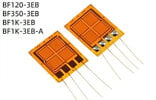
You have a bridge, connected to Vcc, lets say 5V. Its CM V is 2.5V. Its deviation
you have to compute, but for this example, when bridge unbalanced ranges
+/- 100 mV. So its output ranges from 2.6V to 2.4V.
Your arduino, says its running off 5V, the A/D input range is 0 - 5V.
So you have to translate 2.4V to 2.6 V to 0 V to 5.0 V. So start with G needed.
G = 5V / .2V = 25. So that gives you the slope of Vout / Vin.
Now you have to offset that by the CM voltage of 2.5 V so you get 0 - 5 V.
The easy way is to have a - supply as well on AD620 and use a OpAmp
differential circuit to subtract out the offset. A tool you can play with :
Generate Common-Mode Voltage vs. Output Voltage (aka Diamond) plots, using your design criteria. Select your preferred In-Amp from a list of devices that will meet your signal range requirements.

tools.analog.com
A design method for offset OpAmp is :
Of course you dont have to use the entire range of Arduino A/D, you can
trade that off for other considerations.
For negative supply you can use PWM output of Arduino and this :
Everyone needs a negative voltage rail eventually, but most only have a single rail supply. This project will show you how to build a negative voltage generator that runs off a single rail supply!

www.allaboutcircuits.com
View attachment 60416
Because the AD620 has excellent PSRR that should be OK, but doing an error buget or
sim always prudent.
Regards, Dana.