Hello,
Is the current for the complete sensor or for one section?
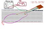
If it is for the complete sensor, the max voltage would be 25 mA X 120 Ohms = 3 Volts.
I found a couple of sites for the sensor, but no specs are given:
 sensor-con.en.alibaba.com
They are typical chinese sites whit hardly any info.
sensor-con.en.alibaba.com
They are typical chinese sites whit hardly any info.
Bertus
Is the current for the complete sensor or for one section?
If it is for the complete sensor, the max voltage would be 25 mA X 120 Ohms = 3 Volts.
I found a couple of sites for the sensor, but no specs are given:
Bf120 Bf350 Bf1000 3eb Full Bridge Strain Gage Price - Buy Full Bridge Strain Gage,Bf1000 3eb Full Bridge Strain Gage,Bf350 3eb Full Bridge Strain Gage Product on Alibaba.com
Bf120 Bf350 Bf1000 3eb Full Bridge Strain Gage Price - Buy Full Bridge Strain Gage,Bf1000 3eb Full Bridge Strain Gage,Bf350 3eb Full Bridge Strain Gage Product on Alibaba.com
Bertus