Maker Pro
Maker Pro

I'm Back- sort of

Audioguru

Sep 24, 2016
3,656
Joined
Sep 24, 2016
Messages
3,656
You do not understand.
Look here:
 

Attachments

  • tone and volume again.png
    tone and volume again.png
    551.2 KB · Views: 11

SparkyCal

Mar 11, 2020
849
Joined
Mar 11, 2020
Messages
849
Audioguru. Thanks. I will get back to this tomorrow afternoon and report back.
 

SparkyCal

Mar 11, 2020
849
Joined
Mar 11, 2020
Messages
849
Thanks again to all. I won’t have a chance to get back to this till later today. But this time around, before I correct things, I am going to force myself to re read each post here, and ensure I understand why things work the way they do. Stayed tuned.,.
 

SparkyCal

Mar 11, 2020
849
Joined
Mar 11, 2020
Messages
849
The good news and the bad news.

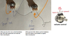
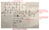
The good news is that I am no longer plagued by the problems I had in the early days. My build on the PCB board went quite well and my multi meter seems to indicate that I am getting the proper reading at the pins. You may call that for the life of me, in the old days, I would never get the voltage divider part of there circuit to work properly, but this time, it does.


The bad news: I am getting absolutely no sound to the amp. After ready everyone's posts on how to wire up my pots, I tried wiring it the way Harald suggested, when he edited my diagram,. So, perhaps I screwed it up, or maybe the pots are still not wired properly.

I really appreciate everyone's time on this, so I am don't know which suggestions to go with.


I will read Harald's link to an in depth review of how to use a pot, but I think using numerous posts (tone and volume) and how they interact, is the part that I find puzzling.
Any ideas?

Thank-you
 

SparkyCal

Mar 11, 2020
849
Joined
Mar 11, 2020
Messages
849
Maybe I will ask it thus way (with reference to Audiogurus' diagram here : https://www.electronicspoint.com/forums/threads/im-back-sort-of.295105/page-2)

So, with reference to that, I think this is what I should be doing:

The Tone pot. Its input prong (left prong) , would go to the 270R resistor, The right prong goes to ground, the middle goes to the input of the next pot. which is the left prong of the volume pot.

Then the ground from the volume (the right prong) goes to ground. The middle is the out to the jack.
 

Audioguru

Sep 24, 2016
3,656
Joined
Sep 24, 2016
Messages
3,656
Maybe I will ask it thus way (with reference to Audiogurus' diagram here : https://www.electronicspoint.com/forums/threads/im-back-sort-of.295105/page-2)

So, with reference to that, I think this is what I should be doing:

The Tone pot. Its input prong (left prong) , would go to the 270R resistor, The right prong goes to ground, the middle goes to the input of the next pot. which is the left prong of the volume pot.

Then the ground from the volume (the right prong) goes to ground. The middle is the out to the jack.
You do not say if the prongs of your pots are pointing up or down.

With no input signal, measure the DC voltages:
 

Attachments

  • distortion maker.png
    distortion maker.png
    362.3 KB · Views: 12

SparkyCal

Mar 11, 2020
849
Joined
Mar 11, 2020
Messages
849
With 9 volts running to it, but no input signal

After R33. 4.47 V

Just after pin 6 and before the 1uF capacitor. 4.06 volts

I realize that the output has to go to a guitar amp.
 

Audioguru

Sep 24, 2016
3,656
Joined
Sep 24, 2016
Messages
3,656
The DC voltages are correct. Maybe you got a cheap fake opamp from "over there".
 

SparkyCal

Mar 11, 2020
849
Joined
Mar 11, 2020
Messages
849
That’s possible but unlikely. I have a ton of the 488ds that I bought via Amazon. The op amp I bought for this circuit came in a 4 pack from my local electronics store prior to Covid hitting. It is a big and reputable store. I also used a socket and tried more that one. I think the issue in in the pot wiring.
 

SparkyCal

Mar 11, 2020
849
Joined
Mar 11, 2020
Messages
849
I recall vaguely something about when using a dual op amp
, you had to do something to buffer the second op amp not being used. Is that true
 

Audioguru

Sep 24, 2016
3,656
Joined
Sep 24, 2016
Messages
3,656
You must disable the unused opamp to prevent it from oscillating and causing interference.
Connect its output to its - input and connect its + input to a half the supply voltage bias.
 

Attachments

  • unused opamp2.png
    unused opamp2.png
    4.6 KB · Views: 9

SparkyCal

Mar 11, 2020
849
Joined
Mar 11, 2020
Messages
849
I am refreshing my knowledge as I go. I just finished watching four YouTube videos on op amps. One of them talked about having two separate power supplies, to make the op amp work. This is the video that confused me. You don’t need two power supplies for what I am going right? Isn’t that taken care of by the voltage divider and biasing the amp?
 
Last edited:

Audioguru

Sep 24, 2016
3,656
Joined
Sep 24, 2016
Messages
3,656
Yes.
With a positive and negative power supply, the +input of the opamp is biased at 0V which is half the total supply voltage.
With a single positive power supply then the + input is biased with a voltage divider at half the supply voltage.
 

bertus

Moderator
Nov 8, 2019
3,367
Joined
Nov 8, 2019
Messages
3,367
Hello,

You might want to read the attached PDF´s on single supply opamp circuits.

Bertus
 

Attachments

  • sloa030a_Single-Supply Op Amp Design Techniques.pdf
    137.3 KB · Views: 3
  • sloa058 A Single-Supply Op-Amp Circuit Collection.pdf
    163.1 KB · Views: 1
  • slyt189 Single-supply op amp design.pdf
    244.1 KB · Views: 1

SparkyCal

Mar 11, 2020
849
Joined
Mar 11, 2020
Messages
849
AudioGuru- thanks. I thought so. Just wanted to make sure I wasn't losing my mind.

Bertus- I think the docs you sent me are worth reading and I plan to. Sometimes, I think I put too much reliance on Youtube videos- after all, anyone can make a video about anything; doesn't mean they are correct. I found that with guitar lessons. There are a million Youtube guitar teachers, but some fo them, despite best intentions, just confuse people. So, reading a legit doc in a good thing.

Speaking of losing my mind: The first time Audioguru asked me to do the readings, they were as I posted them, and hr stated they seemed correct.

Today, I took the same readings.

After R33. 4.46 V

Just after pin 6 and before the 1uF capacitor. 8.89 volts

That second reading changed and seems wrong now. I wonder what caused that. I swapped out the op amp and got the same results. (All my pots, except for the 500K one are disconnected at the moment- but I don't think k it would have anything to do with it). Maybe Bertus' docs have the answer- which I will explore.
 

SparkyCal

Mar 11, 2020
849
Joined
Mar 11, 2020
Messages
849
I just read the first doc you posted Bertus. I will be honest and say that I can't follow the equations or the math, but the point of the article is well taken.

I also learned this:

Single-supply design was considered technically limiting because the older op amps had limited capability. The new op amps, such as the TLC247X, TLC07X, and TLC08X have excellent single-supply parameters; thus, when used in the correct applications, these op amps yield rail-to-rail performance equal to their split-supply counterparts.

This is probably something Audioguru and others have been clobbering me over the head with for some time; older op amps are not reliable for this type of stomp box applications. Interestingly, the article offers some suggestions on which op amps are ideal;. maybe I will get some of those. Maybe the ones I am using are simply breaking down. otherwise, why would the readings change overnight?
 

Audioguru

Sep 24, 2016
3,656
Joined
Sep 24, 2016
Messages
3,656
Sparky Cal, the schematic of your distortion making pedal circuit shows a single opamp with the pin numbers of a single opamp.
BUT you are using a dual opamp with different pin numbers. That is probably why your circuit does not work.
 
Top