Maker Pro
Maker Pro

Inductance circuit

electronicsLearner77

Jul 2, 2015
306
Joined
Jul 2, 2015
Messages
306
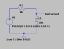
I want to simulate a condition and verify the current behavior in Inductor. The below is the circuit
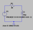
1690448765308.png

The response of the circuit is
1690449535014.png

I want to simulate a case where my input is off pulse goes to 0V, then the current shall flow for certain time in the same direction. I think that is the nature of the inductor but i am not seeing it. What inductor and resistor to be used.
 

Harald Kapp

Moderator
Moderator
Nov 17, 2011
13,771
Joined
Nov 17, 2011
Messages
13,771
56 pH is way too small to show any significant effects at your timescale of ms. Increase the inductance to some mH, e.g.1 H or even higher to see an effect.
You may also reduce the rise and fall times of the pulse to 1 ns.
See this simulation:
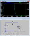
1690452909156.png


Apart from the simulation it's all in the math: V = L × di/dt or di/dt = L / V and obviously with such a small L as in your simulation and a fixed V di/dt will be very small, too. Which in turn means what you see in your simulation is effectively the current through the resistor: I = V/R.
This in turn shows us, that the circuit diagram and the waveforms in your post do not match. With a 5 V pulse and a 2 k resistor you'd see a current of 2.5 mA, not 0.6 mA.
A bit more diligence when posting would be appropriate.

It is also a good idea to label the waveforms and show where they are picked from in the schematic. In this simple circuit it is comparatively easy to guess which is which, but in a larger circuit one loses oversight quickly. Even the author of the simulation will. Trust me ;).
 

bidrohini

Feb 1, 2023
200
Joined
Feb 1, 2023
Messages
200
56 pH is way too small to show any significant effects at your timescale of ms. Increase the inductance to some mH, e.g.1 H or even higher to see an effect.
You may also reduce the rise and fall times of the pulse to 1 ns.
See this simulation:
View attachment 60041


Apart from the simulation it's all in the math: V = L × di/dt or di/dt = L / V and obviously with such a small L as in your simulation and a fixed V di/dt will be very small, too. Which in turn means what you see in your simulation is effectively the current through the resistor: I = V/R.
This in turn shows us, that the circuit diagram and the waveforms in your post do not match. With a 5 V pulse and a 2 k resistor you'd see a current of 2.5 mA, not 0.6 mA.
A bit more diligence when posting would be appropriate.

It is also a good idea to label the waveforms and show where they are picked from in the schematic. In this simple circuit it is comparatively easy to guess which is which, but in a larger circuit one loses oversight quickly. Even the author of the simulation will. Trust me ;).
May I know the name of the simulation software that you used here? Please?
 
Top