Maker Pro
Maker Pro

Massage chair control board help..

Qsilver

Oct 5, 2014
13
Joined
Oct 5, 2014
Messages
13
I have a massage chair that has a blown/main board.
The chair is in Cape Town Africa, and was accidentally plugged into 220vac..
Not 110vac... oops.. At any rate there are no service parts for this board.
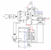
I have drawn a schematic by tracing the components on the board.
Mass Board Olay.jpg MassageChair.png
Unfortunately the chair is located in Africa (I am in Ohio, US).
I have all of the related components with exception of the feedback limits and 2 motors..
The components in the chair were poorly marked, so here is where I could use some help..
I believe the motor U/D-M (carriage up down, is a reversible 120vac capacitor start style)
The DC motor MAS-M (massage motor) voltage is not known... The chair when working operated in 3 speeds.
I believe these speed are controlled by r8-r7-r6.
>> How do I figure out the operating voltage range of the DC motor?

>> Do I need the motors connected to power the board so I can start testing?
>> What could I substitute for the motors? Light bulbs?

Thanks for helping...

Richard
 

KrisBlueNZ

Sadly passed away in 2015
Nov 28, 2011
8,393
Joined
Nov 28, 2011
Messages
8,393
Hi Richard and welcome to Electronics Point :)

So you only have that board?

The mains transformer would probably have failed pretty quickly from the overvoltage. Is that part of the rest of the chair? Can you get it tested? Probably the primary will be open circuit. Sometimes there is a thermal fuse inside the transformer that can be replaced.

The overvoltage from the secondary of the mains transformer through the bridge rectifier at the bottom left of your schematic could also have damaged any number of components on the board. I guess you knew that.

The schematic you posted is a bit too small to read clearly, but I agree with your ideas on the massage motor drive circuit. R6~8 and C1 provide a variable delay on the mains input voltage, to the diac and to the triac to chop the mains waveform like an incandescent lamp dimmer. The chopped waveform goes through a bridge rectifier and a large off-board inductor to the 220 µF capacitor to smooth it. Then it goes through the relay to the massage motor.

You should be able to replace the motor with an incandescent bulb for testing, yes. I suggest using one rated for 220/230V and about 100W. A 110V one would probably be OK too.

I don't know whether the board needs some kind of feedback from the motors. If the motor connectors have only two pins, that implies maybe there's no feedback. But the feedback could be through a separate connector.
 

Qsilver

Oct 5, 2014
13
Joined
Oct 5, 2014
Messages
13
So you only have that board?

The mains transformer would probably have failed pretty quickly from the overvoltage. Is that part of the rest of the chair? Can you get it tested? Probably the primary will be open circuit. Sometimes there is a thermal fuse inside the transformer that can be replaced.
Hi thanks for the look. Not sure why the schematic is small? I can click and enlarge...?

I have all of the components here except the DC motor, AC motor, and the limit switches.

There is no main transformer.. The AC line cord goes to a switch and fuse, then plugs direct to this board.
The 240V MOV is well exploded. The main chair fuse was taken out.
So I am slowly working thru this board.:confused:
 

KrisBlueNZ

Sadly passed away in 2015
Nov 28, 2011
8,393
Joined
Nov 28, 2011
Messages
8,393
That looks like a mains transformer above bridge rectifier DB102 in the bottom left corner. "Mains" transformer, as in AC mains power, not "main". Sorry, down under we refer to the AC wall supply as "mains". What do you normally call it over there?
 

Qsilver

Oct 5, 2014
13
Joined
Oct 5, 2014
Messages
13
That looks like a mains transformer above bridge rectifier DB102 in the bottom left corner. "Mains" transformer, as in AC mains power, not "main". Sorry, down under we refer to the AC wall supply as "mains". What do you normally call it over there?

I just call it line voltage...

Oh... I see what you mean about the transformer. This seems to be the logic supply.
I have not measured it yet but would assume that it's in the range of about 8-9 VAC out. 12VDC rectified for the coil, and board.
Couldn't find any number I could cross on the transformer. See image..

The hybrid CPU board is fully encased in plastic or vinyl. Can only see shadows of components.
 

Attachments

  • Low Volt TX.jpg
    Low Volt TX.jpg
    197.3 KB · Views: 526

KrisBlueNZ

Sadly passed away in 2015
Nov 28, 2011
8,393
Joined
Nov 28, 2011
Messages
8,393
The smoothing capacitor on the output of the bridge rectifier is rated for 25V according to your diagram, so I guess the voltage will be more than 8~9V but not sure how much. So is that the transformer that was exposed to the 220V AC? If so, you'd better check the output voltage.

The "hybrid CPU board" is the black thick film module mounted vertically on the PCB, right? Yeah, I hope that's not damaged, because that's almost certainly a custom device made for that company only.
 

Qsilver

Oct 5, 2014
13
Joined
Oct 5, 2014
Messages
13
Yes I figure that I have a 50/50 of the cpu being good.
The system main fuse was taken out, but a 2nd board in the system was also fried.
Will start checking things...
Any way to guess what DC motor voltage is for MAS-M..
If I uses a lamp, what wattage?
 

KrisBlueNZ

Sadly passed away in 2015
Nov 28, 2011
8,393
Joined
Nov 28, 2011
Messages
8,393
Any way to guess what DC motor voltage is for MAS-M..If I uses a lamp, what wattage?
In post #2 I said:
You should be able to replace the motor with an incandescent bulb for testing, yes. I suggest using one rated for 220/230V and about 100W. A 110V one would probably be OK too.
The maximum DC voltage you can get from bridge rectifying 115 VAC is about 160V. That's why I suggested a 230V bulb.
 

Qsilver

Oct 5, 2014
13
Joined
Oct 5, 2014
Messages
13
MassageChair Test jumpers.png So I was able to test the low voltage/logic part of the board.
It appears to still function:) The remote responded and the directional relay energized.
That confirmed working, now I have to go to the high voltage side and start testing.

If anyone else ever needs to test this board, you have to connect the jumpers that tell the chair that the car is up and thumpers wide. See diagram. Oh, this is a Interactive Health EMS.9 chair from about 1996-98
 

Attachments

  • MassageChair Test jumpers.png
    MassageChair Test jumpers.png
    305.8 KB · Views: 773

hardyboyj

Feb 17, 2015
4
Joined
Feb 17, 2015
Messages
4
Hello Qsilver and all.

I have the same chair and it bit the bullet about a year ago. I finally decided to try and repair it and unplugged the various wires from the circuit board inside the massage chair. Now I am trying to put the board back in and of course several of the plugs are the same and unfortunately the length of the wires can reach either plug locations.

I am hoping you would be kind enough to either photograph a closeup of the wires going to the circuit board or could provide a description (ie: color codes) of the wires going to the circuit board.

That would save me from potentially making an error and hearing "I told you so" from my wife.

Thanks.
 

Qsilver

Oct 5, 2014
13
Joined
Oct 5, 2014
Messages
13
Hello Qsilver and all.

I have the same chair and it bit the bullet about a year ago. I finally decided to try and repair it and unplugged the various wires from the circuit board inside the massage chair. Now I am trying to put the board back in and of course several of the plugs are the same and unfortunately the length of the wires can reach either plug locations.

I am hoping you would be kind enough to either photograph a closeup of the wires going to the circuit board or could provide a description (ie: color codes) of the wires going to the circuit board.

That would save me from potentially making an error and hearing "I told you so" from my wife.

Thanks.

There are 2 files attached. Follow the jumper ID's on the schema..
Oh.. There is a slightly later revision where the power is on a 2nd board and no inductor.. CN12-1 CN12-2
The board text labels kind of make sense also.
Hope this helps... Overview Board sm.jpg MassageChair.png
 

Qsilver

Oct 5, 2014
13
Joined
Oct 5, 2014
Messages
13
As a general update I was able to repair this board and now it works once again..
 

hardyboyj

Feb 17, 2015
4
Joined
Feb 17, 2015
Messages
4
Thanks guys for the pictures, I now have the connections back where they are supposed to be but unfortunately the original problem with my chair is still there, even after attempting the reset procedure provided by the manufacturer.

The remote light stays on and beeps but as soon as I flip the power switch on the side of the chair the relay close to the top left side of the diagram above simply "clicks" and nothing else happens. The red light remains on the remote control but nothing happens inside the chair.

Any advice any of you could provide would really be appreciated. I'm not afraid to troubleshoot things but require detailed instructions. The obvious question is what would cause that really to just "click".

Thanks,

hardyboyj
 

Qsilver

Oct 5, 2014
13
Joined
Oct 5, 2014
Messages
13
The relay clicking is a good thing. That means the CPU is functioning..
The relay controls the massage motor direction. MAS motor rotating one way changes the spacing of the pressure wheels.
The other direction oscillates them.
If you look near the massage motor there is a flat plate with three small magnetic limit tubes.
The Chair start position is wide, and CAR up..
Try turning the motor by hand both directions. (power off)
You will see in one direction the spacing of the wings changes.
( This corresponds to the control wide, medium, and narrow)
Watch the indicator arm over the limits. Move it to wide and try again.
 

hardyboyj

Feb 17, 2015
4
Joined
Feb 17, 2015
Messages
4
Hello Qsilver, thanks for your help.

I once again tried the reset procedure and paid more attention to the massage motor to see if the massage arms and rollors were doing anything and they did nothing. The massage mechanism moves up with no problems when the chair is powered on.

The massage motor belt (and associated arms and rollors) works well when turned by hand but nothing happens when powered on. How can I go about troubleshooting to see if my problem is the motor or perhaps one of the transformers? I guess at this point I should trace the wires from the motor to the circuit board and make sure everything is connected firmly at each end. I should then disconnect the remote control to make sure it is not providing a "short circuit" to the circuit board causing a problem with the massage motor? Then maybe (I remember my uncle doing this on motors in his repair shop sometimes) giving the massage motor a few taps with a screwdriver to see if it starts turning? Any idea what the voltage level is for this motor? I'm guessing if that is the problem finding a replacement is pretty near impossible.

Any more suggestions????
 

Qsilver

Oct 5, 2014
13
Joined
Oct 5, 2014
Messages
13
Hello Qsilver, thanks for your help.

I once again tried the reset procedure and paid more attention to the massage motor to see if the massage arms and rollors were doing anything and they did nothing. The massage mechanism moves up with no problems when the chair is powered on.

The massage motor belt (and associated arms and rollors) works well when turned by hand but nothing happens when powered on. How can I go about troubleshooting to see if my problem is the motor or perhaps one of the transformers? I guess at this point I should trace the wires from the motor to the circuit board and make sure everything is connected firmly at each end. I should then disconnect the remote control to make sure it is not providing a "short circuit" to the circuit board causing a problem with the massage motor? Then maybe (I remember my uncle doing this on motors in his repair shop sometimes) giving the massage motor a few taps with a screwdriver to see if it starts turning? Any idea what the voltage level is for this motor? I'm guessing if that is the problem finding a replacement is pretty near impossible.

Any more suggestions????

Ok.. So I understand, you are able to move the carriage up and down with the remote..
If you select the kneading button does the red light turn on? (I assume yes)

The mas motor is DC. I don't know the voltage.
In the circuit, you can see R8,R7,R6. Theses correspond to the 3 speed settings.
(try to select the different speeds also)
To measure voltage see image set the remote button to kneading red light...
This is calling for the mas-m to turn on. The relay controls direction.
If you switch between Tapping and Kneading, you should hear the relay click.

No Mass Motor.jpg

The resistor is here in circuit. You can also see the speed resistors, the Tria-and Diac. and rectify.

Mass Drive Section.jpg
 

Attachments

  • EMS-9-s-remote.jpg
    EMS-9-s-remote.jpg
    18.2 KB · Views: 387

hardyboyj

Feb 17, 2015
4
Joined
Feb 17, 2015
Messages
4
Hello again. I'm sorry I didn't make myself clear on what happens when I flip the power switch (the one on the side of the chair) to on. As far as the remote goes the red light stays on but all buttons simply beep when I push them.

If I follow the manufacturer reset procedure by turning the main power off then plugging the chair back into a working wall outlet, then turning the top of the elevation motor counter-clockwise approximately 20 turns, allowing the massage assembly to lower several inches beyond the activation point of the upper limit switch. I then turn the large pulley on the bottom of the gear box counter-clockwise approximately 3 turns. You will see the white magnet holder on the upper shaft of the gear box turn to approximately the 2:00 position. You want to position the white magnet holder so it is NOT over the Glass REED Switch. I then turned the chair ON.

Two things are supposed to happen (in sequence):
- The Massage Mechanism will travel to its top position (THAT WORKS ON MY CHAIR)
- The Massage Arms will rotate until their magnet is set at the 12:00 position (That DOES NOT work on my chair)

So in a nutshell the up/down mechanism works but the massage roller mechanism does not. Hopefully this explanation is clearer.

Thanks,

hardyboyj
 
Top