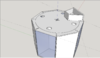
@Inverness: Thank you for your clarification! The 3D CAD concept drawing is also appreciated. I will try to answer the questions you have posed so far, but I am sure there will be other questions and answers brought by you, as well as by other responders. That is the nature of a dialog and the way this forum works best IMO.
When you said the coin slot was horizontal, as opposed to a vertical orientation, I envisioned the coin slot on a typical vending machine (which is usually in a vertical orientation) being rotated ninety degrees to make the coin slot horizontal
but still located in a vertical plane. We now know from your description and 3D CAD image that the "coin slot" is horizontal
and located in a horizontal plane. The difference may or may not be important to how the coin is detected.
It matters that the slot is horizontal as opposed to vertical, because a vertical slot means that the device linked by Externet would be perfectly suitable.
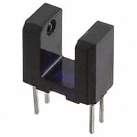
The optical-interrupter type of sensor that
@Externet linked to will work in any orientation, but the opto-electronic components (consisting of an infrared LED and an infrared-responsive photodetector) would probably have to be physically separated from the associated circuitry to provide adequate clearance for the coin drop. Such mechanical separation is shown in
@Externet's image in post #13, but this can be carried much further by cutting the plastic joining the two-wire emitter and the three-wire sensor, thus allowing further physical separation of these two opto-electronic components. Or a completely custom configuration of light emitter and photodetector can be made.
Some edge-guidance of the coin would probably be required, to ensure that one edge passes between the infrared LED and the photodetector. OTOH, if the coin is to be "viewed" edge-on by the opto-electronic device as it falls through an appropriately sized
hole (NOT a slot!), then clearly the separation between the LED light emitter and the photodetector must be larger than the coin diameter. Why you would want to place such an artificial restriction on coin detection is a mystery, at least to me, but it can be done.
A coin on top of the surface is slid over the hole which it drops through. ...
How is this accomplished? Does someone move the coin, laying horizontally, with a finger until the coin is over a hole? Or is the coin held between forefinger and thumb and dropped through a rectangular horizontal slot of appropriate length and width, whereupon the coin lands on a rotating horizontal plate which carries it toward various diameter holes that will presumably somehow select coins of different diameters? How is that accomplished, exactly?
... The coin needs to be registered and counted. There are different coins of different denominations that are legal tender. But the slot sensor doesn't need to differenciate [sic] between different coins because I have one slot for each coin. ...
Does your reference to "one slot for each coin" refer to the various sized holes shown in your 3D CAD drawing or does it refer to various sized, multiple, horizontal rectangular slots that are not shown on the drawing? Exactly how does a coin move from the pocket of its owner to end up on the rotating plate? How does the spinning plate center and deposit a coin over an appropriately sized hole? Are you aware of how difficult it is to coaxial align a round coin with only a slightly larger hole so the coin will drop through the hole?
It would be much easier to measure the coin diameter with a frame grabber attached to a digitized CCD camera while the coin is resting on the spinning plate. Software then identifies and sorts the coins by size, dropping each sized coin into the proper bin, perhaps by opening a trap-door in the spinning plate or by deflecting the coin off the plate and into a chute over the appropriate bin with a solenoid actuator. Several hundred coins per minute could be sorted and counted in this manner.
... A spinning plate picks up one coin at a time and slides it over the holes, starting with the smallest size first. If it doesn't fit, it doesn't drop. I just want to register each coin once in order to count it.
Are we re-inventing a coin-sorting mechanism here? That sounds more like a mechanical design problem with electronics just added on at the end to tally the coins that fall through holes. Good luck with that! Wiser heads than you will find here have spent decades refining coin-sorting technology for vending machines. The slot machines in Las Vegas (and elsewhere in the world) couldn't survive without it! Not only do the mechanisms sort coins by value, they also detect many counterfeit coins, which your machine will not do of course. And many will detect "bent" coins that could jam the coin sorting mechanism, and such coin sorters will have a reject lever to remove the "bad" coin and return it to its owner... usually... and if it isn't too bent out of shape.
But it appears (at least to me) that you are trying to create a desktop novelty with no practical value except for the "Gee whiz" exclamations it may evoke. So, I will take a short divergence here to try to explain how opto-electronic devices work. I looked for such a discussion in our resources section, but found nothing. Perhaps I or some other member of EP will attempt to write about it in some depth later. You can also
visit this website for a basic overview of semiconductor optical detectors.
The use of light, in particular collimated beams of light, to detect the presence or absence of physical objects is almost as old as electronics. Originally, light for this purpose was produced by incandescent light bulbs and was therefore a broad-spectrum "white" light. A simple lens collected the light and directed it as a beam, similar to the beam produced by a flashlight. A photodetector received the light beam, again through a simple lens, and focused the beam onto the sensitive area of the photodetector. As long as the light path was uninterrupted, the photodetector could "see" the light source and signal the presence of same. If the light path were interrupted by an opaque object, the photodetector would no longer "see" the light source and would signal that an obstruction had occurred.
That is essentially all there is to optical interrupter types of detectors. Over the years the technology has changed to offer simpler, cheaper, brighter, or more reliable light sources such as LEDs and lasers as well as a wider range of photodetectors. There are also variations on how the light beam is interrupted: a co-located photodetector with an LED light source can be used with a retro-reflector (or corner-cube reflector) to detect light path interruptions over longer path lengths. The advantage is all the electronics is in one location, and separate wiring for the photodetector and light source is not required. Also, the range is easily extended with plane mirrors.
Early photodetectors were cadmium sulfide (CdS) light-dependent resistor (LDR) cells. These are still dirt cheap, very sensitive to changes in light intensity, and simple to make, but they have many disadvantages. I won't go into that here, but LDRs are generally NOT acceptable when fast response to changing light conditions is required.
Here is a datasheet for a typical CdS photocell.
Vacuum photo-diodes were next used, particularly ubiquitously for motion picture sound reproduction. Later developments along those lines include photomultiplier tubes, which are still used today when extremely low light levels must be detected with very fast response times. An excellent description of the huge variety available can be found in
this Hamamatsu PDF manual.
The real breakthrough technology came with the development of the bipolar junction transistor or BJT. It was soon discovered that PN junctions respond to light, and that transistor action would amplify the effect to useful signal levels. Phototransistors, photodiodes, and photo-triggered SCRs (solid state rectifiers) soon followed. All of these semiconductor devices respond to visible as well as near-infrared wavelengths, their response peaking near 900 nanometers wavelength in the near infrared. If infrared response is the ONLY desired response, a device may be packaged in what appears to be opaque plastic, but the plastic actually passes near-infrared wavelengths quite well while blocking visible light. This helps prevent, but does not eliminate, false positives caused by other nearby illumination sources.
Opto-electronic devices require some understanding of physical optics to be successfully applied. The illumination field and its intensity must be specified or determined. The required sensitivity of the photodetector and its range of wavelength response must be specified or determined. Most folks involved in electronics do not have the knowledge, experience, or skills necessary to specify or design opto-electronic solutions, but today that isn't strictly necessary. There are plenty of commercial off-the-shelf (COTS) solutions available for virtually any opto-electronic sensing application. The problem is finding something suitable for your particular problem. If you are an industrial customer, vendors and manufacturer's reps will usually be more than willing to help you select one of their products as the correct "solution," but winnowing the chaff from the wheat can be very time consuming. Fortunately there is Google to help with this. Use it aggressively and often to narrow down your search for possible solutions before turning here for advice and help. Keep an open mind: there are many alternative solutions to every solvable problem.
Getting back to answering your questions...
The circuit linked to in post #2 features an LDR, but I'm wondering what exists in optical sensors, and trying to narrow the selection down by trying to state my concerns or possible issues.
Hobbyists use LDRs for many reasons, chief of which is probably cost. The resistance range as a function of light intensity is huge, being a few hundred ohms with strong lighting to several million ohms when placed in totally dark conditions. It can take several hours for an LDR to reach it's maximum dark resistance but only a few milliseconds for the resistance to drop to the minimum resistance when fully illuminated. The resistance versus illumination characteristic is highly non-linear.
The next most popular optical sensor is the photo-diode. These can range from a device packaged much like an LED to a simple silicon solar cell to a sophisticated PIN photo-diode, the latter being usually operated in reverse-biased avalanche mode from a current-limited source to provide nano-second or pico-second response times to pulsed light sources.
Your application is probably best served by a common silicon photo-diode packaged like an LED. Photo-diodes have two modes of operation: voltage generation mode and reverse-biased current mode. The current mode is very linear in its response to light intensity whereas the voltage generation mode is simpler to configure and use, especially for on/off type detection applications.
Phototransistors are also available, consisting of an ordinary NPN transistor with the emitter-base and base-collector junctions deliberately exposed to external illumination by means of transparent packaging at the wavelengths of interest. Some packaged opto-isolators use a phototransistor to improve their sensitivity.
... I wonder if whatever optical sensor you use is sensitive enough to ambient light to trigger a false positive. Is there something I could do to mitigate this, besides enclosing the chamber/room?
This is a common problem. There are several different approaches that may yield a viable solution. The first, and easiest, solution is to narrow the optical bandwidth using light emitters producing a specific narrow range of wavelengths, followed by optical bandwidth filters in front of the photodetector. LEDs produce light having a narrow range of wavelengths, as of course do lasers. Red and near-infrared are common emitter wavelengths that are used and colored plastic filters limit the bandwidth of optical radiation reaching the photodetector. Narrowing the optical bandwidth is often effective because ambient light sources are usually broadband in nature. By limiting the range of detectable wavelengths, the photodetector becomes less sensitive to interference from light sources outside that range.
The most common way to eliminate responses (false positives) from external, ambient, light sources is to modulate the active emitter, usually by turning it on and off rapidly with a square-wave modulation signal, a process called light chopping. The photodetector is equipped with a synchronous de-modulator that responds only to the chopped illumination. Chopping frequencies of several kilohertz are possible with inexpensive emitters and photodetectors, yielding rapid response times in the millisecond range. A block diagram and more information can be found at
this website.