Maker Pro
Maker Pro

Op Amp Circuit Gain Does not Match LTSpice Simulation

epsolutions

Sep 7, 2019
116
Joined
Sep 7, 2019
Messages
116
I would prefer DC coupled because there is a need to preserve the wave shape at low frequencies. But I am open to suggestions, if the DC coupling is what is limiting/clipping gain at output.

The input is approx line level audio. It is a bipolar signal with a +/-1.5V swing.

Many thanks for your input so far.
 

danadak

Feb 19, 2021
797
Joined
Feb 19, 2021
Messages
797
Is this more what you want ?

1709768229394.png

Regards, Dana.
 
Last edited:

epsolutions

Sep 7, 2019
116
Joined
Sep 7, 2019
Messages
116
Thank you for sending that circuit. This is how LTSpice simulates it. Since there seems to be a recurring discrepancy between different sims, and sims and real life, I will not add further to this thread but rather research elsewhere and get back if and when I can provide some useful information.
 

Attachments

  • Op Amp Emitter Follower Mod 1.png
    Op Amp Emitter Follower Mod 1.png
    59.3 KB · Views: 1

Harald Kapp

Moderator
Moderator
Nov 17, 2011
13,771
Joined
Nov 17, 2011
Messages
13,771
why does the sim (.asc file attached) show an output of twice of what I am measuring in the constructed circuit?
But how is this related to the offset, or some other factor?
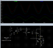
The simulation uses a model of the real circuit (opamp). Any model makes simplifications to speed up simulation time. Example: set the supply voltage V1 to 9 V:
1709788956498.png
The simulation shows an output voltage of 8 V whereas in a real circuit the output voltage of the opamp is limited to ~ 7 V (V1 - 2V), cf. post #13 or see the datasheet. Subtract 2 × BBE for the base-emitter juctions of Q1 and Q2 the output at the emitter of Q2 can be max. ~ 5.8 V.
Or in other terms for the output voltage to reach 9 V, the opamp's output voltage needs to be at least 10.2 V. Add the top margin of ~ 2 V ( Vsupply - Vopamp) and the supply voltage needs to be at least 12.2 V (minimum) or 13.2 V when assuming a 3 V margin (again, see the datssheet).

The simulation also shows the voltage at the output of the opamp to go to -100 kV. You do agree that this is unrealistic, do you?

You need to be aware of the limitations of a simulation. Any simulation needs to be taken with a grain of salt, especially when the real circuit shows a different behavior. Looking not only at the obvious points of interest (Vout) but inspecting other nodes as well helps to identify potential issues (Vopamp).
 

danadak

Feb 19, 2021
797
Joined
Feb 19, 2021
Messages
797
Using a R-R OpAmp we get some better results :

1709812231452.png

Choice of OpAmp dictated by what was already in sim, eg. spice model. A general
purpose RRIO OpAmp will pretty much do. Note slew rate of OpAmp shown probably a
little light, you need something on the order of 1.25 V/uS min for 20 Khz input.

You obviously need to heat sink the 3055 output transistor.


Regards, Dana.
 
Last edited:

Ylli

Jun 19, 2018
409
Joined
Jun 19, 2018
Messages
409
Danadak, recheck your schematic. You have the feedback resistor connected to the op-amp output, it should be connected to the top of the inductor.
 

danadak

Feb 19, 2021
797
Joined
Feb 19, 2021
Messages
797
Thanks Ylli for catching that, here is updated schematic :

1709868820932.png

I checked the phase margin, that looks OK as well.


Regards, Dana.
 
Last edited:
Top