Maker Pro
Maker Pro

Question about ACS758 current sensor

Andy.wpg

Apr 8, 2015
19
Joined
Apr 8, 2015
Messages
19
I am just in the initial "I wonder if I could" stage of designing a current sensing device for my R/C model aircraft.

The idea is a unit that plugs in between the battery and the aircraft to see how much current is being used when the motor(s) are running, to better get an idea of battery life under use when setting things up. I'm planning on using the 100A version of the ACS758 https://www.allegromicro.com/~/media/Files/Datasheets/ACS758-Datasheet.ashx

My question is, can I use the battery under test as the power source for my MCU and associated circuitry (LCD, etc)? Or is this going to cause problems for the measurement? I attached a picture I found on a website that shows typical connections. but it doesn't show where the Arduino is getting its power from.

Anyone have any ideas on this? It would be nice to not have a separate battery to power the unit.

Thanks

Andy

upload_2019-3-10_10-13-23.jpeg
 

davenn

Moderator
Sep 5, 2009
14,271
Joined
Sep 5, 2009
Messages
14,271
Anyone have any ideas on this? It would be nice to not have a separate battery to power the unit.


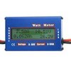
As an alternative there is a ready made unit for around AU$12.00 from Ebay


Ideal for what the OP wants :)

tho on another note, I wouldn't want to try and have 100A ( or anything close to it) going through those thin cables ;)
 

Bluejets

Oct 5, 2014
6,983
Joined
Oct 5, 2014
Messages
6,983
tho on another note, I wouldn't want to try and have 100A ( or anything close to it) going through those thin cables ;)

Yeah...model gear is a bit over-rated as to what it can handle.
I think somewhere they say the unit is 50A with 100A being intermittent.
Just how intermittent is not quoted but I guess it covers their ass ....:D

I think with many of the previous sensors, it is possible to add external shunts but given the Ops obvious experience level , I doubt it would be a good move.
 

hevans1944

Hop - AC8NS
Jun 21, 2012
4,889
Joined
Jun 21, 2012
Messages
4,889
... As an alternative there is a ready made unit for around AU$12.00 from Ebay...
https://www.ebay.com.au/itm/Digital...hash=item592153be1e:m:mIrAjDLK6WURUM1pzEefQbQ
View attachment 44823
I like this idea, especially if there is no telemetry involved, just a pre-flight check on the ground. Unfortunately OP lives in Canada and the vendor at the link shown does not ship to Canada. OTOH, here is a link for what is probably the same Asian product that will ship to Canada for $US 8.00 plus $US 2.30 shipping and handling.

The ACS758 is NOT recommended for new designs, said advice being prominently displayed on the datasheet, along with suggestions for alternative parts. But if you aren't digitizing to perform airborne telemetry, then use whatever you can get for a one-off project, and maybe purchase a few spares.
 

davenn

Moderator
Sep 5, 2009
14,271
Joined
Sep 5, 2009
Messages
14,271
Yeah...model gear is a bit over-rated as to what it can handle.
I think somewhere they say the unit is 50A with 100A being intermittent.
Just how intermittent is not quoted but I guess it covers their ass ....:D

I think with many of the previous sensors, it is possible to add external shunts but given the Ops obvious experience level , I doubt it would be a good move.


I use the same style of thing ... different make .... inline with my ham radio gear, peak current is around 20- 22A with 100W TX
 

Andy.wpg

Apr 8, 2015
19
Joined
Apr 8, 2015
Messages
19
Thanks for the replies!

I had not come across the pre-made meter and will probably go that route.

It’s getting so that there’s nothing left to create on your own anymore! Someone’s already built it and is selling it on EBay for far less than it would cost to build.

*sigh* maybe I’ll come up with something one of these days!
 

Harald Kapp

Moderator
Moderator
Nov 17, 2011
13,758
Joined
Nov 17, 2011
Messages
13,758
Someone’s already built it and is selling it on EBay for far less than it would cost to build.
Do it yourself is not only about saving money. In fact, as you noticed, you may end up spending a lot more money. But you get the fun, the added knowledge and the satisfaction out of your own work - things you don't get when buying an off the shelf product.
The off the shelf product may give you a quick start so you have time to ponder your own, possibly better solution while already using the product.
 

Andy.wpg

Apr 8, 2015
19
Joined
Apr 8, 2015
Messages
19
Although I will likely buy the commercial one, I still may breadboard this to play with it.

My original question remains, can I use the battery under test to power my circuitry?

My thoughts were that since the current is essentially flowing through a short and is isolated from the Hall Effect Sensor, using the battery to run a 7805 to get my +5V rail should be fine. Of course, the current to run the extra circuitry would be part of the total current, but that’s milliamps and not a factor really.

Or am I just letting out the smoke by trying this?

BTW, I was aware that the quoted device was not for new designs, this isn’t a commercial application and is going to be a one off.

Thanks again everyone!
 
Last edited:

hevans1944

Hop - AC8NS
Jun 21, 2012
4,889
Joined
Jun 21, 2012
Messages
4,889
It’s getting so that there’s nothing left to create on your own anymore!
That is absolutely NOT TRUE. With the availability of free application development software and really cheap microprocessors, the only limitation to creativity is your imagination.

Back in the 1970s, when microprocessors were just becoming available, it required a small fortune to breadboard, program, and troubleshoot an embedded application. Today, with on-chip programming, it costs less than a hundred bux to get started with, for example, Microchip PIC microprocessors or one of the "single board" Arduino type microcontrollers.

As @Harald Kapp said, it isn't about cost. It's about the experience. I didn't study for, and obtain, an amateur radio license (call sign AC8NS) so I could talk to anyone, anywhere, in the world... my cell phone pretty much already takes care of that. My amateur radio license does allow me to do that, but only with fellow travelers who are also amateur radio operators. So, no robo-calls in ham radio yet. No data fees or caps either.

I love participating in amateur radio for a plethora of reasons, but only a few of those reasons are related to verbal communication. One of the reasons is very much the thrill of creating something new and personal for me, whether it is my own idea or the careful reproduction (perhaps with modifications) of someone else's idea. Sure, cost is a consideration, but it isn't the impetus driving what I do.

A few years ago I met a new friend here on EP who also happened to be a woodworker. I also work in wood, but my skills are more like those of a woodbutcher... I am mainly skilled at making sawdust. My friend takes his hobby and his health seriously, providing his powered woodworking machine tools with a dust collection system consisting of a central vacuum system and a distribution of collection hoses to various tools such as table saw, band saw, jointer, planer, etc. He wanted a circuit that would detect when he turned on any one or more of the powered woodworking tools, so as to activate the dust collection system. The dust collector would continue to run for a short period after the last tool was turned off to allow time to clear the distribution hoses.

Easy peasy, right? Just insert an Allegro current sensor in the line providing power to the tools, cobble up a delay-on-release time delay relay to control the dust collector, maybe add some logic and... voila! Mission accomplished. Project done.

Well, it wasn't quite that easy! Peruse that rather lengthy thread to see what we accomplished. The Allegro responds to both AC and DC currents. So we had some "extra" circuitry to accommodate that. His shop also included both 120 VAC as well as 240 VAC power tools, so two Allegro current sensors were needed. And finally, it turned out that a simple PIC microprocessor was the simplest way to provide the delayed-off timing. I never did discover whether there is an inexpensive Asian product that does the same thing, but I am sure we both had a lot of fun and we both learned a lot about PICs.
My original question remains, can I use the battery under test to power my circuitry?
Sure, but I would use a switch-mode buck converter to get 5VDC from 12 VDC. More efficient than dropping all that voltage across a 7805. Again, buck converters are dirt cheap from Asian sources, especially since you don't need much current at 5 VDC.
 

Andy.wpg

Apr 8, 2015
19
Joined
Apr 8, 2015
Messages
19
That is absolutely NOT TRUE. With the availability of free application development software and really cheap microprocessors, the only limitation to creativity is your imagination.

Back in the 1970s, when microprocessors were just becoming available, it required a small fortune to breadboard, program, and troubleshoot an embedded application. Today, with on-chip programming, it costs less than a hundred bux to get started with, for example, Microchip PIC microprocessors or one of the "single board" Arduino type microcontrollers.

As @Harald Kapp said, it isn't about cost. It's about the experience. I didn't study for, and obtain, an amateur radio license (call sign AC8NS) so I could talk to anyone, anywhere, in the world... my cell phone pretty much already takes care of that. My amateur radio license does allow me to do that, but only with fellow travelers who are also amateur radio operators. So, no robo-calls in ham radio yet. No data fees or caps either.

I love participating in amateur radio for a plethora of reasons, but only a few of those reasons are related to verbal communication. One of the reasons is very much the thrill of creating something new and personal for me, whether it is my own idea or the careful reproduction (perhaps with modifications) of someone else's idea. Sure, cost is a consideration, but it isn't the impetus driving what I do.

A few years ago I met a new friend here on EP who also happened to be a woodworker. I also work in wood, but my skills are more like those of a woodbutcher... I am mainly skilled at making sawdust. My friend takes his hobby and his health seriously, providing his powered woodworking machine tools with a dust collection system consisting of a central vacuum system and a distribution of collection hoses to various tools such as table saw, band saw, jointer, planer, etc. He wanted a circuit that would detect when he turned on any one or more of the powered woodworking tools, so as to activate the dust collection system. The dust collector would continue to run for a short period after the last tool was turned off to allow time to clear the distribution hoses.

Easy peasy, right? Just insert an Allegro current sensor in the line providing power to the tools, cobble up a delay-on-release time delay relay to control the dust collector, maybe add some logic and... voila! Mission accomplished. Project done.

Well, it wasn't quite that easy! Peruse that rather lengthy thread to see what we accomplished. The Allegro responds to both AC and DC currents. So we had some "extra" circuitry to accommodate that. His shop also included both 120 VAC as well as 240 VAC power tools, so two Allegro current sensors were needed. And finally, it turned out that a simple PIC microprocessor was the simplest way to provide the delayed-off timing. I never did discover whether there is an inexpensive Asian product that does the same thing, but I am sure we both had a lot of fun and we both learned a lot about PICs.

Sure, but I would use a switch-mode buck converter to get 5VDC from 12 VDC. More efficient than dropping all that voltage across a 7805. Again, buck converters are dirt cheap from Asian sources, especially since you don't need much current at 5 VDC.


Don’t get me wrong, I’ve been using PICs for years and have made a few things that I could have bought, but wanted to tweak a little.

I think I was more lamenting the fact that I can’t seem to come up with an original idea. Everything seems to have been done before.

Thanks for the idea on the buck converter. Since my plan was to make a device capable of working with 2-6S LiPo batteries I’ll have to make sure the limits are ok with whatever device I get.

BTW, VE4RDO here.....

Thanks for the interesting reply!
 
Last edited:

Bluejets

Oct 5, 2014
6,983
Joined
Oct 5, 2014
Messages
6,983
Sure, but I would use a switch-mode buck converter to get 5VDC from 12 VDC. More efficient than dropping all that voltage across a 7805. Again, buck converters are dirt cheap from Asian sources, especially since you don't need much current at 5 VDC.

May not be possible as I mentioned before given the floating nature of the shunt.
Also , as I noted before, most converters are common ground output.
ACS758-Functional-Block-Diagram.jpg
 

Harald Kapp

Moderator
Moderator
Nov 17, 2011
13,758
Joined
Nov 17, 2011
Messages
13,758
My original question remains, can I use the battery under test to power my circuitry?
Yes.
May not be possible as I mentioned before given the floating nature of the shunt.
But: the chip is referenced to ground. So if ground is connected to battery "-" everything is should be fine.
Note that the sensor in this chip is not a shunt, it is a hall sensor which senses current by the effect of the current's magnetic field, Therefore there is no electrical connection ( apart from some small parasitic capacitance) between the input curent and the measuring circuit.
 

hevans1944

Hop - AC8NS
Jun 21, 2012
4,889
Joined
Jun 21, 2012
Messages
4,889
The biggest problem IMHO in using the Allegro chip is the analog output is offset to half the supply voltage when there is zero current present. So, for a typical 5 VDC supply, the output swings from about +2.5 VDC to 0 VDC for increasingly negative currents and from about +2.5 VDC to +5 VDC for increasingly positive currents. The output is an analog signal that is proportional to the input current and the power supply potential. A ratiometric analog-to-digital conversion is necessary to remove this sensitivity to power supply voltage. Many PIC A-to-D converters do this automagically, but the programmer/designer needs to be aware of what is going on.

@Bluejets: you need to be aware, as @Harald Kapp pointed out, that the Allegro senses the magnetic field produced by current flowing through its measuring circuit. The measuring circuit is NOT a shunt. It is an isolated, floating, conductor (of suitable size) that produces a magnetic field when current flows through the conductor. The Hall-effect sensor creates an analog voltage that is proportional to that magnetic field, but to accommodate both negative and positive currents when operating from a single uni-polar power supply, the analog output for zero current input is offset by an amount equal to half the supply voltage. The offset voltage is generally of no consequence when measuring DC currents (it can be subtracted out in software or nulled out in hardware), but considerations must be made when measuring AC currents with an analog-to-digital converter to ensure that conversions occur at appropriate points on the analog waveform. Easiest way to accomplish this is to capacitively couple the Allegro analog output signal and then rectify and filter the resulting AC signal to a produce a smooth DC signal suitable for measuring.
 

Harald Kapp

Moderator
Moderator
Nov 17, 2011
13,758
Joined
Nov 17, 2011
Messages
13,758
A simple method overcoming these issues (incl. the "not recommended for new designs" issue) is a low side current sensor as described e.g. in this article. In this application there are only positive currents to be measured (unless you want to operate the motor as generator, which I doubt in this case). The current sense resistor will, however, introduce a certain loss.
 

Andy.wpg

Apr 8, 2015
19
Joined
Apr 8, 2015
Messages
19
A simple method overcoming these issues (incl. the "not recommended for new designs" issue) is a low side current sensor as described e.g. in this article. In this application there are only positive currents to be measured (unless you want to operate the motor as generator, which I doubt in this case). The current sense resistor will, however, introduce a certain loss.


The offset may be a useful thing. That way, the meter could be used when charging as well. That was in the back of my mind when I chose the bi-directional version.

Thanks for the low side current sense application. Haven’t seen that before and it gives me more food for thought.
 

sumeryamaner

May 29, 2017
50
Joined
May 29, 2017
Messages
50
The rationale of "being not recommended for new designs" is the end of production of this line of sensors.

You can use the battery under test to power the Arduino board. You can use a regular 7805. I have built a power analyser using the ACS712-5A sensor and an Attiny85 with OLED display. As my current consumption is low, I am using a LM2950-5.0V as regulator and supply my microcontroller circuit from the battery under test. A couple of mA wouldn't have a negative effect on the accuracy because voltage measurement with Atmega/Attiny is already not too accurate.
 
Top