Alistair Ballantyne
- Nov 16, 2020
- 36
- Joined
- Nov 16, 2020
- Messages
- 36
Thanks for getting back to me but apologies, I have no idea what you mean.If I may be so bold... The gentleman is teaching you about reference designators..
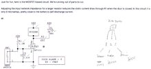
View attachment 63017
Felt positive I made the right connections but I am obviously doing something wrong?