Maker Pro
Maker Pro

Simple transistor circuit problem

rasklangus

May 19, 2013
18
Joined
May 19, 2013
Messages
18
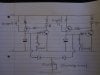
Hello, I am a novice experimenter with a basic understanding of electronics. I have made a circuit which uses a Darlington transistor to switch an LED on with a capacitor and variable resistor connected so the led will fade over an adjustable period of time. This bit of the circuit works great. I also want the option for the LED to stay on after the trigger is released until a reset button is pressed. I thought I could achieve this by joining the emitter and the base of the transistor so once triggered the base would be fed from the emitter and remain open. This doesn't work. I am obviously missing a vital bit of understanding as I can't see why. Could somebody more knowledgeable than myself (that's probably everybody reading this:) please explain why this doesn't work and possibly suggest what I might do to fix it? I have attached a picture of the circuit...

Thanks very much,

David.
 

Attachments

  • circuit diagram.gif
    circuit diagram.gif
    90.3 KB · Views: 188

CDRIVE

Hauling 10' pipe on a Trek Shift3
May 8, 2012
4,960
Joined
May 8, 2012
Messages
4,960
You won't be able to latch it with a single BJT.

Chris
 
Last edited:

rasklangus

May 19, 2013
18
Joined
May 19, 2013
Messages
18
Hi Chris, can you explain why? I would like to know what I'm not understanding.

thanks.
 

CDRIVE

Hauling 10' pipe on a Trek Shift3
May 8, 2012
4,960
Joined
May 8, 2012
Messages
4,960
Because the Emitter of a BJT is ~0.7V lower than the Base. Since your BJT is a Darlington, which is two BJT's in a single package, it will be ~1.4V lower than the Base.

Chris
 

CDRIVE

Hauling 10' pipe on a Trek Shift3
May 8, 2012
4,960
Joined
May 8, 2012
Messages
4,960
Just a note here. I wrote single FET in my first reply but I edited that, as it should have read BJT. I have no idea why I saw a FET in your schematic. Maybe because I party hearty on Saturdays. :D

Chris
 

KrisBlueNZ

Sadly passed away in 2015
Nov 28, 2011
8,393
Joined
Nov 28, 2011
Messages
8,393
Right. You can't "latch" the voltage across the capacitor by feeding the voltage from the emitter back to it. The emitter voltage is about 1.3V lower than the base voltage. That's not the only reason.

What you're looking for is a "sample and hold" circuit, where the capacitor can hold its charge indefinitely. Well, no capacitor is perfect; there is always some leakage, but you can get a reasonable approximation of a continuous "hold" if you (a) disconnect the discharge resistance completely, and (b) reduce the current drawn by the transistor.

A Darlington doesn't draw much base current, because it has such a high current gain, but it does draw a little bit. You can make a three-transistor Darlington, or even a four-transistor Darlington; each transistor you add will reduce the base current by a factor equal to the current gain of the new transistor. (Each transistor will also increase the base-emitter voltage drop by another 0.7V or so, as well.)

So you could connect another Darlington transistor in Darlington configuration with the existing one, then when you disconnect your 15M discharge potentiometer, the capacitor will hold its charge for quite a while. Not forever, but quite a lot longer than before.
 

CDRIVE

Hauling 10' pipe on a Trek Shift3
May 8, 2012
4,960
Joined
May 8, 2012
Messages
4,960
Or he could do this. LED2 is used in place of a more expensive Zener or a 3 stack of 1N4002's or 1N914's.

Chris
 

Attachments

  • DarLatch.JPG
    DarLatch.JPG
    37 KB · Views: 222
Last edited:

rasklangus

May 19, 2013
18
Joined
May 19, 2013
Messages
18
Thanks, and heres another silly question.

Thanks Kris and Chris, sorry I haven't posted sooner, I wasn't meaning to be rude, I have been away for a few days. I now understand about the base-emitter voltage drop (0.7v or 1.4v for a Darlington pair). I have adopted a circuit like Chris suggested with a PNP single transistor and an NPN Darlington (a complimentary latch I believe). It works great, Thanks for the help.

Chris, I did think that you had made a mix up with the FET/BJT but I didn't want to correct you as I am an obvious novice :) I do now have another problem which you will probably think just as stupid, haha!

...So, I now want to connect many of these circuits together in a way that allows that an array of LEDs to be triggered and discharged independently but so they share the 15M potentiometer so the discharge time for all the LED's can be controlled from one knob. However, connecting more than 1 circuit through the same pot just means that triggering any individual circuit lights all the LEDs. I thought by putting a Diode in each line between the pot and each circuit would fix this but it doesn't. This is probably an obviously stupid thing to do but again, if my understanding can be improved I would be very grateful for any explanation. I have attached another terrible looking drawing :)
 

Attachments

  • IMG_1638.jpg
    IMG_1638.jpg
    141.5 KB · Views: 219

CDRIVE

Hauling 10' pipe on a Trek Shift3
May 8, 2012
4,960
Joined
May 8, 2012
Messages
4,960
At this point it would be best to fully describe your project.

Chris
 

rasklangus

May 19, 2013
18
Joined
May 19, 2013
Messages
18
Hi Chris, what I have described is essentially the whole project. It is a large array of LEDs all located right beside their triggers which are activated through touch and fade over a definable length of time. They will be spaced on a 20mm grid (or as close as they can be as the circuit is gradually growing:) It is an interactive piece for an art installation. All components are SMD technology and once I have a working prototype I will be paying to have the boards manufactured. What I have shown in the drawing on the previous post is essentially the entire project but with only 2 circuits instead of 20000.
 

rasklangus

May 19, 2013
18
Joined
May 19, 2013
Messages
18
I should add that the 'reset' function will work in the same way as the timer in that all the individual LED circuits will run through 1 switch.
 

rasklangus

May 19, 2013
18
Joined
May 19, 2013
Messages
18
In case that wasn't explained well, people will be able to write their name in lights or draw a smiley face or whatever by touching the walls of a giant box in the middle of a room. Whatever they have drawn will fade gradually over 30 seconds or so.
 

BobK

Jan 5, 2010
7,682
Joined
Jan 5, 2010
Messages
7,682
You would be far better off using microcontrollers for this. One microcontroller could control many LEDs and having a single reset and fade control would be trivial.

Bob
 

rasklangus

May 19, 2013
18
Joined
May 19, 2013
Messages
18
I know nothing about microcontrollers I'm afraid BobK (you may say I know nothing about doing it this way either :) Im sure I could learn tho. I am however going to complete this project with discrete components if possible. This current project uses 80,000 leds. could one microcontroller do that?
 

BobK

Jan 5, 2010
7,682
Joined
Jan 5, 2010
Messages
7,682
80000? I hope your budget it large.

In answer to your question. Yes, but with help. It would not be practical to control them all with 1. I would make a standard panel with maybe 4 x 4 and have each panel have it's own microcontroller.

My question is how many components do you think it is going to take to control 80000 LEDs?

My second questions is this. 80000 LEDs on a 20mm grid will fill a 56 meter square. Where are you going to put this?

Edited: Whoops, my math was wrong, it is a 5.6 meter square. Still pretty large though!

Bob
 
Last edited:

rasklangus

May 19, 2013
18
Joined
May 19, 2013
Messages
18
Your maths was right at 56m2! The project is actually 20m2 Bob. 80000 would have been the amount needed to do 20m2 with a 15mm grid which was the original intention. As you rightly say though, the cost is the prohibitive factor and also to include the little circuit as attached in a previous post (even in tiny SMD packages) on a 15mm grid is pushing it so 20mm it is (and testing has proved that 20mm spacing is still visually acceptable). Including the LEDs, the component cost per circuit is 10p adding in PCBs and pick and place assembly and I'm looking at £400/m2. The installation is a giant cube in a gallery space.
 

rasklangus

May 19, 2013
18
Joined
May 19, 2013
Messages
18
Of this £400/m2 the component cost for the control circuits is only actually about £25. I realise that there would be far less components to place if using shift registers or multiplexers so the assembly cost would be reduced but the PCBs and LEDs would remain the same. I assumed that for the sake of a simple reliable circuit which I could develop myself without much fuss the independent circuits would be the way to go. I don't know how much the microcontrollers would be to control 2500 LEDs (1m2 at 20mm grid spacing) but I assumed they would be more than £25.
 
Last edited:

rasklangus

May 19, 2013
18
Joined
May 19, 2013
Messages
18
After reading a bit about shift registers and multiplexers and charlieplexers I have some reservations; It seems the more LEDs there are on an array the more they share the actual 'on' time. I need really bright light (my current proposed LEDs are white 6000mcd and when they are powered full time they are about bright enough There are ways around this apparently but it seems to raise more problems. I really don't want any flickering, (as in it would spoil the whole thing) A 'digital' fade always seems to be noticeable and I really don't want this either. The analogue nature of the proposed circuit is appealing, the fade from the capacitor decay is aesthetically pleasing and the fact that they are all going to fade slightly differently gives a nice effect.
 

rasklangus

May 19, 2013
18
Joined
May 19, 2013
Messages
18
Also there is the option of not controlling the fade time with a variable resistor connected to all the circuits and just using a fixed resistor for each circuit. This would not be ideal but would do if there is no obvious solution to my problem without including lots more passive components.
 

BobK

Jan 5, 2010
7,682
Joined
Jan 5, 2010
Messages
7,682
I would use a 64-pin micro to control 7x7 LEDs with an individual driver for each one, no multiplexing. Cost of the micro is < 1 pound, and you would need 7 ULN2003 driver chips (nice how that works out 7 drivers per chip). And you are at 3-4p per LED
for those components.

I would use a double sided board with the LEDs on one side and the micro + drivers + electrical connections on the other. The switches could possibly be capacitive touch. What were you planning on doing for switches? I find it hard to believe your 10p cost per unit with discrete components.

Bob
 
Top