Maker Pro
Maker Pro

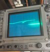
Tektronix 465 oscilloscope with garbled display

PluggerWorks

Jul 6, 2023
14
Joined
Jul 6, 2023
Messages
14
I've been fixing vintage audio for a while, thought I would try to fix this oscilloscope. I don't really know where to begin on these however. I can't find any videos or threads referring to a "garbled display" like I have, though there is probably a better term for it.
I did check the DC low voltages, and they are within spec except for one (1548). I do have the service manual. If anyone has any pointers on where to begin, that would be great. Pics show Channel 1 and 2, there is nothing connected to the inputs.
358740421_3515451615386609_1089197089370740591_n.jpg 358350740_228382293451962_4229713539855538581_n.jpg


Test Point

Should be

Measured

1536

55

54.6

1548

15

12.4

1568

5

5

1568

-8

-8

1518

110

111
 

Delta Prime

Jul 29, 2020
2,138
Joined
Jul 29, 2020
Messages
2,138
Welcome to Make you a Pro!
465 ABCDEFG which one do you have I'll tell you what we'll start off with b
 
Last edited:

Delta Prime

Jul 29, 2020
2,138
Joined
Jul 29, 2020
Messages
2,138
I have a question?
In your profile you state that you work for a company called plugger works. And in the photo of the oscilloscope I could see very high ceilings with exposed conduit almost as if you were in a commercial building.
I have no problem helping you out but I do have a problem doing your job. Unless of course you're willing to grease the wheels a little bit.
$$$$
;)
 

PluggerWorks

Jul 6, 2023
14
Joined
Jul 6, 2023
Messages
14
That made me chuckle. I'm retired from the IT world, and picked up audio repair as a hobby, created a business called Plugger Works, as a catch all for the various types of efforts I plug away at. So I am a one man show, and you're seeing the exposed ceiling of my basement workshop. I've been trying to teach myself to read schematics and troubleshoot various electrical problems as they come up, but without formal training or a lifetime of experience, it is tedious. Sometimes I think I'm getting it, then others I feel so lost.

I was able to find a section in the manual you provided that is explaining trying to isolate the 15 volt circuit. I got most of the decoupling done, but could not find L891 or VR896, despite the note to look at the "adjustment locations 1". I tried looking at each circuit board page, still couldn't find them anywhere. Disconnecting the 1,2,4,5,6 the voltage is up to 14 from 13.2, but not up to 15.

I really was curious as to whether with the display that I have, is this a fixable problem, or is it just a blown CRT and not worth bothering with?
 

PluggerWorks

Jul 6, 2023
14
Joined
Jul 6, 2023
Messages
14
My version doesn't have a letter, the faceplate just says 465. Serial on faceplate says B307768.
After watching that video - If I find a bad component that requires this whole beast to be disassembled, I'm not sure I have to juice for that!
 

Delta Prime

Jul 29, 2020
2,138
Joined
Jul 29, 2020
Messages
2,138
That made me chuckle
Okay I believe you.
Can I move into your basement?
But seriously,yeah you got to have to tear that puppy apart. In order to get to the test points and components involved to replace, desoldering and soldering.
But if you're okay with that, Heck, I wouldn't mind helping you out. But I must warn you I'm a little bit of a.....


Crackpot.jpg
 

Bluejets

Oct 5, 2014
7,057
Joined
Oct 5, 2014
Messages
7,057
If anyone has any pointers on where to begin, that would be great
Start looking in the power supply section, mainly for any electrolytics that are bulging, leaking or simply have a low capacity or esr test.
For the latter, removal would be essential.
 

Delta Prime

Jul 29, 2020
2,138
Joined
Jul 29, 2020
Messages
2,138
Purely speculative could be a case of intermodulation,deflection amplifier.
Does the CRT makes noise when you pick it up turn it sideways. Like broken glass. Would you happen to have a frequency generator? Do you have a video camera you can place so you can play back where all the screws go.Let's tear this sucker apart. You have the service manual, let's get to it. What do you say? Looks like fun.
 

Delta Prime

Jul 29, 2020
2,138
Joined
Jul 29, 2020
Messages
2,138
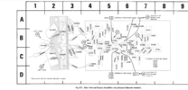
If you feel up to it, this is Paige 149 in the service manual vertical deflection amplifier I mean no offense because of your prior experience with audio I presume you know how to read schematics
Here's some quick checks make sure you have these voltages at the checkpoints.


Screenshot_20230706_211809.jpg
Below is the board itself parts placement.

Screenshot_20230706_211707.jpg
Or you can lay back and watch videos...
Movie night!!
EatingPopcorn.gif
 

73's de Edd

Aug 21, 2015
3,640
Joined
Aug 21, 2015
Messages
3,640
Sir PluggerWorks . . . . .

After viewing this . . . .

+5V rail is bad, down to 4V and has a FIERCE 3V ripple level riding it .
The 5000µF capacitor has declined down to 250µF and it ESR's out as 140 Ohms.
C1552 a 5000uF.


With having all of that high level of a ripple voltage . . . . just modulating and distorting the H**l out of a vert sweep trace, doesn't it just look like that it would be your problem.

Now, head off to the power supply portion . . . . . to at least initially, shunt across the installed capacitor, with 1000's of ufds, whilst observing the trace pattern. ( ITS A MIRACLE ! )
Then . . . . . . Git 'er done !

Thaaaaaaaaaaaaasssit

73's de Edd . . . . .

Nurse says :
"We need a stool sample and a urine sample."

Since I'm a bit hard of hearing, I then ask my wife . . . . . "What did she say?"
She then says: "They want your underwear."

tenor.gif

.
 
Last edited:

Delta Prime

Jul 29, 2020
2,138
Joined
Jul 29, 2020
Messages
2,138
Hello,

Bama has also manuals for different revisions available:

Bertus
Pretty sure the table of content would probably change as well. It can be quite difficult navigating through a service manual per the thread starters request.
I like to go old school original who's unfortunately days are numbered
This is the service manual I am referring to.
Screenshot_20230707_105602.jpg
 

PluggerWorks

Jul 6, 2023
14
Joined
Jul 6, 2023
Messages
14
1. no sound of anything loose or broken when I shake it around
2. Thanks for all the responses! I think with your all's help I can do this!
3. That video looked almost exactly like my screen!, though my 5v test point on the power supply shows 5v.
4. The screen shots you posted are much better than what I have in my copy of the manual, maybe I'll find a different version to look at.
5. I have a signal generator, another working oscilloscope, signal tracer, volt meters, ESR meter, desoldering gun, soldering iron.
6. I will start checking things following your suggestions now.
 

PluggerWorks

Jul 6, 2023
14
Joined
Jul 6, 2023
Messages
14
Just for clarity - I have the version of the scope with the "discrete version" of the Vertical Output Amplifier, not the IC version . This is mine:
1688757446511.png
 

PluggerWorks

Jul 6, 2023
14
Joined
Jul 6, 2023
Messages
14
I tested the 5 big caps on the power supply board, as best as I could figure out.
One of them seems bad, but please verify that I'm testing correctly. You can see from the pics the cap leads that I am using for test points.
The values were as follows (staggered to mimic the placement on the board, when the scope is sitting on its back end.
1688761484037.png

1542 has a 47 ESR. I also had a lot of trouble getting it to discharge, it was very slow to discharge, even when just using a straight 14g wire. It still registered a couple of volts.
358654578_227961090126010_1889479380923033134_n.jpg355967442_1454688415288389_2944407849331000923_n.jpg
 

Delta Prime

Jul 29, 2020
2,138
Joined
Jul 29, 2020
Messages
2,138
9,9,9. There may or may not be other components in parallel with those capacitors.
In order to keep the cards straight we will use your particular service manual so others may not be confused as well as myself. can you find the component layout along with associated schematic in service manual which you're making these measurements? could you post a photo so we're all on the same page please. thank you.
 
Last edited:

PluggerWorks

Jul 6, 2023
14
Joined
Jul 6, 2023
Messages
14
Thanks for the advice on discharging completely. I have all 5 caps down to 0 volts now, and took fresh ESR readings.
All are 0.15x except for C1542, which is now showing 49.0.
I am working from this page of the manual, page 211 of the tek-465.pdf manual. This version has my "discrete" vertical amplifier as opposed to only the IC version.
1688778470253.png

Page 120 of that manual shows the specs for the capacitors:
1688778627280.png
Power supply caps: page 211


C15623000 mf35v+100-10%
C15131200 mf100v+75-10%
C1512550mf100v+75-10%
C15425500 mf30v+100-10% 49.0 on ESR : should be replaced?
C15525000mf25v+100-0%

This is what I could find at Mouser.com. It doesn't have +100,-10%, it has +75-10%. I don't know how critical that is. I was thinking the new one would go inside that aluminum can so that it can be wired to the 3 ground points, but this one from Mouser is 35mm diameter, and the cans are only 25mm. So how does one replace these caps?

1688779260471.png
 

PluggerWorks

Jul 6, 2023
14
Joined
Jul 6, 2023
Messages
14
I found a thread in another forum that offered this chart of replacements, and these are more feasible to get, and fit, and cheaper too.
The question remains, do I go ahead and replace C1542 with the bad ESR, or is other troubleshooting recommended first?


1688781042663.png
 
Top