Maker Pro
Maker Pro

Tektronix 465 oscilloscope with garbled display

Delta Prime

Jul 29, 2020
2,138
Joined
Jul 29, 2020
Messages
2,138
Ron childress Is well respected. This is your show! is completely up to you following his advice . We are at the point of finding and replacing capacitors while observing the waveform of the scope traces themselves.With that said...We will follow your lead as to what direction you wish to proceed. The answer to your question concerning the measurement obtained using ESR (Equivalent Series Resistance) meter is yes replace the capacitor with a new one.
 

Delta Prime

Jul 29, 2020
2,138
Joined
Jul 29, 2020
Messages
2,138
Also.. thank you for sharing the information of the service repair manual. As you just witnessed it leaves no questions unanswered.
Bravo!
P.S.If there are questions unanswered that would be entirely my fault which is usually the case.:cool:
 
Last edited:

PluggerWorks

Jul 6, 2023
14
Joined
Jul 6, 2023
Messages
14
Great. I will get the caps ordered and replaced, and see where I stand after that. So it will be a few days before you hear back from me, but I look forward to continuing this trek! Thanks for the continuing feedback.
 

PluggerWorks

Jul 6, 2023
14
Joined
Jul 6, 2023
Messages
14
I need some guidance on getting these filter cans removed so I can swap the capacitors. I was able to remove some solder, but it is largely just defying me. I have a solder powered vacuum extractor, which got some solder removed. I've tried with my ksger iron, I've tried with a weller 100/140 gun. Is there a trick? (working on 1542)
361144845_660434206129628_2273671672064716830_n.jpg

Screenshot 2023-07-14 214816.png
 

Attachments

  • 1689385463540.png
    1689385463540.png
    248.8 KB · Views: 3

Delta Prime

Jul 29, 2020
2,138
Joined
Jul 29, 2020
Messages
2,138
Flux rosin core euclidic
Sn.63% Tin/Pb.37% Lead.Solder.
Melts,wets at a lower temperature.
Then Sn.60% Tin/Pb.40% Lead.
Solder pads, look like they took a beating!
Perhaps, game of lights & Shadows?
 

PluggerWorks

Jul 6, 2023
14
Joined
Jul 6, 2023
Messages
14
Great news folks! With the new cap installed, I now get normal waves! I will go thru the calibration steps to see if I can make any adjustments, but it is functional once again! I added the blue jumper wires to carry the ground to the other posts that the cap can used to supply.
361080871_954810175785472_2181336606063189245_n.jpg

361125057_1459401634813644_8860928451901947977_n.jpg
 

Delta Prime

Jul 29, 2020
2,138
Joined
Jul 29, 2020
Messages
2,138
Great news folks! With the new cap installed, I now get normal waves!
Congratulations! post number 11 bullseye.

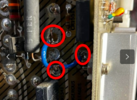
Jumper solder connections unacceptable.
Contaminants such as grease & metal oxide may prevent a good soldered joint from taking place.
It usually becomes noticeable when the solder fails to bond to dirty surfaces.
Red circles in the photo.
Also... Always tin the leads of your jumpers first.

photo_1689392540537.png
 
Last edited:

PluggerWorks

Jul 6, 2023
14
Joined
Jul 6, 2023
Messages
14
I think you are saying the jumper wires are ok, but not the solder joints. I can remove them and do better. I was considering trying to fit the new cap into the old can, since it would sit tight to the board and be more sturdy over time. Right now the only thing holding that new cap in place are its two solder joints. Or I guess I could try to get some hot glue in there.

Now that it is actually working, should I still replace the other 4 big caps, or leave it at just the one. I'm thinking that's a silly question.
 

Delta Prime

Jul 29, 2020
2,138
Joined
Jul 29, 2020
Messages
2,138
I think you are saying the jumper wires are ok, but not the solder joints. I can remove them and do better. I was considering trying to fit the new cap into the old can
9,9,9. For our German friends.
For you. No, No, No.
Jumpers should be solid wire not multi-strand to avoid The frayed wires that are unsoldered.
Flat to the PCB. But I also recognize the difficulties in these modifications as to positioning of the soldering iron and the jumper wires themselves.
As far as capacitors go... 9,9,9. Diameter of capacitors should be the same. One could find two capacitors exact same DC working voltage, along with capacitance but the dimensions would be different. You could find a capacitor that would fit inside the other and that would be a mistake. You say you work on vintage audio.
Now you're working on vintage oscilloscopes. The repair process is the same, replaced with components as close as possible to the original manufacturer specifications. That's the best anyone can do.
 

kellys_eye

Jun 25, 2010
6,514
Joined
Jun 25, 2010
Messages
6,514
Soldering looks ok to me. Stranded wire is no particular issue either. If you are keen to keep the OEM look then stuffing the capacitors is 'standard practise' to restorers of this type of equipment. Feel free!
 

Delta Prime

Jul 29, 2020
2,138
Joined
Jul 29, 2020
Messages
2,138
Soldering looks ok to me. Stranded wire is no particular issue either.
Very informative.
Perhaps some silly putty & little bit of silver paint to make it look like solder.
My crystal ball can also be used as an ocular prosthesis if you wish to borrow it.


photo_1689455424991.png
 

PluggerWorks

Jul 6, 2023
14
Joined
Jul 6, 2023
Messages
14
1. These are solid core wire, the top joint has a large hole because the old can had a mounting tab that was soldered in there. I suppose I could try to pretty it up by filling in that hole with something. But anything I do here would be for cosmetics. Not to say that isn't important.
2. The caps I bought are 22mm and the can is 25mm. I wasn't able to find anything with the pin spacing to match the pcb holes, which is why the new cap won't sit quite flush to the pcb, but it is close. Trying to mount the new cap inside that can looks like a large scale PITA to me, I'm not inclined to pursue that.
 

Delta Prime

Jul 29, 2020
2,138
Joined
Jul 29, 2020
Messages
2,138
But anything I do here would be for cosmetics. Not to say that isn't important.
It is not a matter of aesthetics.
A properly soldered joint will have a concave shape and be symmetrical. This assures proper heating distribution & electrical contact or conduction resulting in a negligible resistance and or impedance.
A skilled eye can see an improper soldered joint.
These are solid core wire, the top joint has a large hole because the old can had a mounting tab that was soldered in there

If you say, that is, a single solid core jumper wire then I believe you.
 

Delta Prime

Jul 29, 2020
2,138
Joined
Jul 29, 2020
Messages
2,138
Trying to mount the new cap inside that can looks like a large scale PITA to me, I'm not inclined to pursue that
Very well.... You leave me no choice! I'm moving into your basement, next week. :p
No harm no foul. Do as you wish, as I stated,this is your show. I'm just a long for the ride.
EatingPopcorn.gif
 
Top