Sirchawlez
- Mar 8, 2023
- 9
- Joined
- Mar 8, 2023
- Messages
- 9
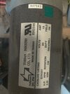
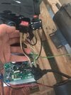
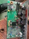
Hey there everybody, I know there are a million different videos and such regarding this topic but I think I may be the one odd ball who managed to collect multiple treadmill motors/boards that are not the normal/typical boards seen in the videos, I say this because I don't see on any of the boards any obvious place to attach a potentiometer, I have purchased multiple pots from 5k-100k and also purchased a pwm controller, I'm happy to use either I'm just attempting to understand where exactly to connect them to be able to control speed on the motors, any help would be greatly appreciated and I am fully aware working with ac can be dangerous and will be using all safety measures to avoid any injury to myself, I'm not a total noob with electronics I just don't want to risk hooking this up incorrectly and burning out a $100+ dollar board in the process, here are a couple pictures of the motors and boards I have collected, you opinions on which motor/board to use for easiest setup/use is also appreciated! I wish I got one of the simple boards that have an obvious 3 connectors for pot placement but these boards apparently don't have that from I could tell. Anyways here they are and thanks in advance for anyone who is willing to take the time to reply, if feeling adventurous feel free to point out the spots for connections on the pictures to simply things even moreso, once I have this setup correctly I plan on making a video for it since I don't see any videos with these boards out there and will happily give credit to whomever helps me in figuring this out! one motor has 2 wires coming from it, the other has 3 red blk and ground, and the third has 4 wires red and blk and two blue.
Attachments
-
 16782973111975070822815215228058.jpg259.3 KB · Views: 6
 -
 16782973383715180942394176565158.jpg223 KB · Views: 5
 -
 16782973621154804456623087064202.jpg310.5 KB · Views: 5
 -
 16782974033358877589676571194142.jpg470 KB · Views: 6
 -
 16782974184841988084225374156859.jpg302.2 KB · Views: 6
 -
 16782974279349032923205867625974.jpg308.5 KB · Views: 6
 -
 16782974592432554072412173669510.jpg295.2 KB · Views: 7

")