Maker Pro
Maker Pro

Tv oled not turn on

Kevin555

Sep 18, 2023
18
Joined
Sep 18, 2023
Messages
18
hello everyone I have a problem with an oled tv (lg 55eg910v) which does not turn on but the red led is on I have several questions

firstly what voltage should be present on the main card in standby mode I do not have only 3.5 volt no trace of 12 and 24 volt

secondly what should happen when I press the on button on the TV should the main board send a signal to the power board to send the 12 and 24 volt voltages on the main card as well as on the tcon card thank you in advance for your answers
 

Externet

Aug 24, 2009
897
Joined
Aug 24, 2009
Messages
897
Guessing !, your 3.5V can be a standby supply (3.3V) always-on to respond to remote control or local buttons.
Not getting other supply voltages after commanding to turn on; the supply circuit can be in protecting-state or at fault. It is convenient to look at its schematic to discern how it works and where to probe. If you do not how it works, you cannot fix it.
 

Kevin555

Sep 18, 2023
18
Joined
Sep 18, 2023
Messages
18
Guessing !, your 3.5V can be a standby supply (3.3V) always-on to respond to remote control or local buttons.
Not getting other supply voltages after commanding to turn on; the supply circuit can be in protecting-state or at fault. It is convenient to look at its schematic to discern how it works and where to probe. If you do not how it works, you cannot fix it.
I know how it works basically, you don't have to be an engineer for that, I know that there is a chip that will command the power board to send the right voltage when I press the power button except that nothing happens, I checked the voltage at the chip terminal when I pressed the power button it went from 3.5 volts to less than 1 volt before going back up is this normal, how do I know if it's Is the chip faulty or is something else blocking its normal operation?
the famous chip has the reference 100GEA
 

kellys_eye

Jun 25, 2010
6,514
Joined
Jun 25, 2010
Messages
6,514
I know how it works basically,
Not from the description you are giving......

I know that there is a chip that will command the power board to send the right voltage when I press the power button
What chip would that be?

I checked the voltage at the chip terminal
Which terminal?

the famous chip has the reference 100GEA
Generic in-house code. Chance of obtaining details of which is ..... 0

Most TV switch-on faults lie with dry capacitors that often manifest themselves as swollen or leaking (sometimes showing no external issues which makes diagnosis harder). As per @Externet the chances of fixing it without a schematic or reasonable prior experience of such devices is low-to-zero.

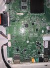
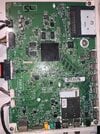
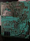
Post some pics of what you did, where you tested/measured and of the main PSU module and we'll take it from there.
 

Kevin555

Sep 18, 2023
18
Joined
Sep 18, 2023
Messages
18
Not from the description you are giving......


What chip would that be?


Which terminal?


Generic in-house code. Chance of obtaining details of which is ..... 0

Most TV switch-on faults lie with dry capacitors that often manifest themselves as swollen or leaking (sometimes showing no external issues which makes diagnosis harder). As per @Externet the chances of fixing it without a schematic or reasonable prior experience of such devices is low-to-zero.

Post some pics of what you did, where you tested/measured and of the main PSU module and we'll take it from there.
hello kellys_eye thank you for your response

so I use a diagram found on the internet I give you the links of the diagram because it is too large for the attachments

( https://www.electronica-pt.com/esqu...k,8033ce31a88e970db794197062dd4f5e/no_html,1/ )

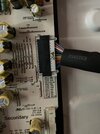
then the chip I am talking about is which for me manages the start of the general power supply (IC 3000) I measured at terminal 36 of the chip because it is to this terminal that the track is related (key2) which goes towards the power button, so when I press the power button once the voltage at terminal 36 drops slightly before going back up and if I press longer it goes below 1 volt as long as I don't let go then when I let go it goes back to 3.5 volts but still no reaction, on the power supply board there are no real problems visually the capacitors after testing on the air ok and the voltages on the primary part of the board seem to correct but on the secondary part of the power supply board no voltage apart from these famous 3.5 volts for standby, I don't really know where to look.

Do you have any idea what steps I should take?
 

Externet

Aug 24, 2009
897
Joined
Aug 24, 2009
Messages
897
Page A18 shows a pertinent P2300 with pins 1 to 8 in need of probing. But I ignore what DPC, DPIM mean or if those are active low or active high command signals. Did not follow where they come from. Pages 6, 7 show diagnosing procedures. Block is on page 28, more on sheet 8.
Suggest you print the schematic to be able to find things. Cannot stand a manual with more than one page is numbered "page 6" and others !:mad:
 

Kevin555

Sep 18, 2023
18
Joined
Sep 18, 2023
Messages
18
here are the diagrams
 

Attachments

  • LG+55EG910_55EG910-ZB+ED51E.part1.zip
    3 MB · Views: 8
  • LG+55EG910_55EG910-ZB+ED51E.part3.zip
    1 MB · Views: 7
  • LG+55EG910_55EG910-ZB+ED51E.part2.zip
    3 MB · Views: 7

Kevin555

Sep 18, 2023
18
Joined
Sep 18, 2023
Messages
18
La page A18 montre un P2300 pertinent avec des broches 1 à 8 nécessitant un sondage. Mais j'ignore ce que DPC, DPIM signifient ou s'il s'agit de signaux de commande actifs bas ou actifs élevés. N'a pas suivi d'où ils viennent. Les pages 6, 7 montrent les procédures de diagnostic. Le bloc se trouve à la page 28, plus sur la page 8.
Suggérez-vous d'imprimer le schéma pour pouvoir trouver des choses. Impossible de supporter un manuel avec plus d'une page est numéroté "page 6" et d'autres !:fou :
Merci pour votre réponse

J'ai mesuré la tension sur P2300 et j'ai 0 volt sauf sur les bornes où il est dit 3,5 volts même lorsque j'appuie sur le bouton d'alimentation3F87F407-A144-4579-B278-2D2EBC609DB7.jpeg
 

Attachments

  • 1A8A8A62-E16F-4C02-818C-FB0766CB7E70.jpeg
    1A8A8A62-E16F-4C02-818C-FB0766CB7E70.jpeg
    439.5 KB · Views: 5

Kevin555

Sep 18, 2023
18
Joined
Sep 18, 2023
Messages
18
I would like to point out that if it is necessary to change a component, I have the skills and equipment I need. I do not want to buy a new power supply card or main card unless this is the last option to consider.
 

bertus

Moderator
Nov 8, 2019
3,383
Joined
Nov 8, 2019
Messages
3,383
hello,

how is the splitted zipfile created?
the same program should recreate the file again.
i use 7zip many times.

bertus
 

Kevin555

Sep 18, 2023
18
Joined
Sep 18, 2023
Messages
18
hello,

how is the splitted zipfile created?
the same program should recreate the file again.
i use 7zip many times.

bertus
I used winrar but to be able to attach it I modified the extension to .zip
 
Top