Maker Pro
Maker Pro

Understanding The Following Circuit

Rajinder

Jan 30, 2016
568
Joined
Jan 30, 2016
Messages
568
Hi All,
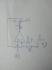
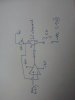
I was wondering if someone can help me understand the attached circuit.
this is what i have measured:-

Input to the opamp is -0.5V (from a PSU), because of feedback the inverting terminal must be at the same potential ie -0.5V because of virtual earth of opamp.
The gate of the FET is at 0.34V, source is at -0.5V (held there by pin 2 of the opamp), drain is at 0V, VGS = 0.82v and VDS = -0.5V.

Is my analogy correct, the n channel is working because the drain is more positive than the source i.e. 0V > -0.5V
Also the gate is more positive than the source i.e. 0.34V > -0.5V.
the VGS(th) of the FET is 0.6V, so am i correct in saying that i have a potential divider arrangement with the 0.84V at VGS, drain at -0.5V whch leaves 0.34V at the gate?

The output is then simply -0.5V/1M = 0.5uA (negative current)

I get the following witha -1.5V at pin 3, pin 2 is also at -1.5V, gate is 0.66V, source is at -1.5V, VGS = 0.84, VDS = 1.5V. So again am i right in saying 1.5-0.84 = 0.66 the gate voltage.

Is the FET in triode mode operation?

I would really appreciate any help.
Best regards,
Raj
 

Attachments

  • opamp2.jpg
    opamp2.jpg
    103 KB · Views: 122

Sunnysky

Jul 15, 2016
541
Joined
Jul 15, 2016
Messages
541
weird circuit. O/P is actually an I/P.

The function may be to protect Vin(-) pin2 and FET clamps it to Vin(+) if external 1M point goes more negative than Vin(+) reference. , otherwise FET is off.
input bias currents will deterimine actual triode operation. with no current on 1M
 

Rajinder

Jan 30, 2016
568
Joined
Jan 30, 2016
Messages
568
Hi, thanks for your help. The circuit is to generate a negative current, so the o/p is an I/p as you correctly say. My understanding was that whatever we have at +Vin , we see at -Vin, due to the source at the same potential ie. Clamps it at that voltage. So do we then get a potentiometer effect, one side at the same potential I.e. Vin, The gate as the wiper and drain at a constant 0V. The wiper adjusts itself to keep Vin clamped and provided that vgs is greater than 0.6V. Could you explain the triode mode for me?
 

Sunnysky

Jul 15, 2016
541
Joined
Jul 15, 2016
Messages
541
triode mode= ohmbic= linear mode. i.e. voltage controlled resistor
 

hevans1944

Hop - AC8NS
Jun 21, 2012
4,889
Joined
Jun 21, 2012
Messages
4,889
What is this? Cobble up a circuit and see if it works? Where is the source that will drive pin 2 negative? Is the bottom end of O/P connected to anything?
 

Rajinder

Jan 30, 2016
568
Joined
Jan 30, 2016
Messages
568
Hi, pin3 is connected to a negative supply. Pin2 is connected to the input of a Carbon Monoxide sensor, which needs a negative current.
The idea being the pin3 of the opamp is the reference, the FET keeps pin 2 at same potential as pin3 of the opamp. Then the resistor at pin2 (which is a 10K) will provide the current I.e. voltage at pin2/10K. The current can change because Vin pin3 of the opamp can be adjusted by the external PSU.
Best regards,
Raj
 

hevans1944

Hop - AC8NS
Jun 21, 2012
4,889
Joined
Jun 21, 2012
Messages
4,889
Raj, the only way that the MOSFET can provide a current through the resistor is if there is a negative voltage at the bottom of your diagram, said voltage applied to the other terminal of the CO sensor which then conducts the negative current provided by the resistor. Even then, unless the CO sensor has a zero impedance, there is no way that the bottom of the resistor is maintained at a constant voltage, which is necessary for the resistor to conduct a constant current. If there is a way to supply a negative voltage to the bottom end of the resistor, then the op-amp will adjust the conductance of the MOSFET to maintain the voltage on pin 2 approximately equal to the voltage on pin 3, plus or minus the small offset voltage of this very excellent op-amp. If this is to produce a constant current through the resistor, then the other end of the resistor must be connected to a constant voltage.
 

Rajinder

Jan 30, 2016
568
Joined
Jan 30, 2016
Messages
568
Raj, the only way that the MOSFET can provide a current through the resistor is if there is a negative voltage at the bottom of your diagram, said voltage applied to the other terminal of the CO sensor which then conducts the negative current provided by the resistor. Even then, unless the CO sensor has a zero impedance, there is no way that the bottom of the resistor is maintained at a constant voltage, which is necessary for the resistor to conduct a constant current. If there is a way to supply a negative voltage to the bottom end of the resistor, then the op-amp will adjust the conductance of the MOSFET to maintain the voltage on pin 2 approximately equal to the voltage on pin 3, plus or minus the small offset voltage of this very excellent op-amp. If this is to produce a constant current through the resistor, then the other end of the resistor must be connected to a constant voltage.
Hi thanks very much for taking time to look at the circuit. If I put a 10K resistor from pin 2 the other end to -5V, would this be another way around the problem. Then negative current could flow through the 1M resistor then to one end of my co sensor, the other end connected to 0V?
I am not 100% sure, if this would work?

My thought was that with drain at 0V, which is more positive than the Source (source strapped to -Vin) that this would allow current flow through the 1M resistor to my CO sensor?

How does the opamp control the MOSFET, I thought it was due the slight difference in mV at the opamp inputs drive the output? Is this correct?

I would really appreciate your help.
Best regards, Raj
 

hevans1944

Hop - AC8NS
Jun 21, 2012
4,889
Joined
Jun 21, 2012
Messages
4,889
... If I put a 10K resistor from pin 2 the other end to -5V, would this be another way around the problem. Then negative current could flow through the 1M resistor then to one end of my co sensor, the other end connected to 0V?
I am not 100% sure, if this would work?
That would allow pin 2 to be driven to the same negative potential (-0.5 V) applied to pin 3. But why not apply -0.5 V from the PSU directly to the 1 MΩ resistor in series with the CO sensor, with the other terminal of the CO sensor connected to 0V? Then you can just ditch that expensive, high-performance op-amp and MOSFET.

My thought was that with drain at 0V, which is more positive than the Source (source strapped to -Vin) that this would allow current flow through the 1M resistor to my CO sensor?
And what would be source of that current? The insulated gate of the MOSFET does not allow the op-amp output to provide any current or voltage to pin 2.

How does the opamp control the MOSFET, I thought it was due the slight difference in mV at the opamp inputs drive the output? Is this correct?
Well, yes, the differential voltage between pin 2 and pin 3 does drive the op-amp output, but negative feedback is required to produce a stable output, which means you have to provide a current or a voltage to the node at pin 2 that is controlled by conduction of the MOSFET. Your original circuit fails to do this. No current flows from the op-amp output to the MOSFET gate.

If you add the 10 kΩ resistor to pin 2, with the other end of the resistor connected to -5 V, the op-amp and the MOSFET will be configured as a negative feedback loop. A negative-going signal at the inverting input (from the -5 V applied through the resistor) drives the op-amp output positive and increases the conduction of the MOSFET. The increased conduction of the MOSFET causes the voltage at pin 2 to go more positive (towards ground) thus implementing negative feedback. Think of the 10 kΩ resistor and the MOSFET as two resistors connected in series between -5 V and ground, the junction of the two being a voltage divider connected to pin 2. As the MOSFET is driven into conduction, pin 2 is driven toward ground or more positive. The output voltage that the op-amp produces to cause the inverting and non-inverting inputs to approach equality depends on the MOSFET transfer characteristics. It is not important as long as it is somewhere between the positive and negative power supply rails and remains in the linear operation region of the op-amp output.

If you connect the additional 10 kΩ resistor and -5 V source, the voltage at pin 2 will follow whatever voltage you apply to pin 3 from the PSU. That does not mean a "constant" current will flow through the 1 MΩ resistor to the CO sensor, even if you connect the other terminal of the CO sensor to ground. The amount of current that flows through the 1 MΩ resistor depends on the impedance of the CO sensor that is in series with it.

Can you provide information on the CO sensor? Manufacturer's name and part number at least, but a datasheet would be even better. Are you planning to measure the voltage drop across the CO sensor? What is the purpose of the PSU output? Why not just connect this directly to the 1 MΩ resistor and CO sensor and then forget about using the op-amp and MOSFET? What is your circuit supposed to accomplish? Please tell us what you are trying to DO. Maybe someone here will be able to tell you how to do it.

@Sunnysky feel free to jump in here at any time.
 

Rajinder

Jan 30, 2016
568
Joined
Jan 30, 2016
Messages
568
That would allow pin 2 to be driven to the same negative potential (-0.5 V) applied to pin 3. But why not apply -0.5 V from the PSU directly to the 1 MΩ resistor in series with the CO sensor, with the other terminal of the CO sensor connected to 0V? Then you can just ditch that expensive, high-performance op-amp and MOSFET.


And what would be source of that current? The insulated gate of the MOSFET does not allow the op-amp output to provide any current or voltage to pin 2.


Well, yes, the differential voltage between pin 2 and pin 3 does drive the op-amp output, but negative feedback is required to produce a stable output, which means you have to provide a current or a voltage to the node at pin 2 that is controlled by conduction of the MOSFET. Your original circuit fails to do this. No current flows from the op-amp output to the MOSFET gate.

If you add the 10 kΩ resistor to pin 2, with the other end of the resistor connected to -5 V, the op-amp and the MOSFET will be configured as a negative feedback loop. A negative-going signal at the inverting input (from the -5 V applied through the resistor) drives the op-amp output positive and increases the conduction of the MOSFET. The increased conduction of the MOSFET causes the voltage at pin 2 to go more positive (towards ground) thus implementing negative feedback. Think of the 10 kΩ resistor and the MOSFET as two resistors connected in series between -5 V and ground, the junction of the two being a voltage divider connected to pin 2. As the MOSFET is driven into conduction, pin 2 is driven toward ground or more positive. The output voltage that the op-amp produces to cause the inverting and non-inverting inputs to approach equality depends on the MOSFET transfer characteristics. It is not important as long as it is somewhere between the positive and negative power supply rails and remains in the linear operation region of the op-amp output.

If you connect the additional 10 kΩ resistor and -5 V source, the voltage at pin 2 will follow whatever voltage you apply to pin 3 from the PSU. That does not mean a "constant" current will flow through the 1 MΩ resistor to the CO sensor, even if you connect the other terminal of the CO sensor to ground. The amount of current that flows through the 1 MΩ resistor depends on the impedance of the CO sensor that is in series with it.

Can you provide information on the CO sensor? Manufacturer's name and part number at least, but a datasheet would be even better. Are you planning to measure the voltage drop across the CO sensor? What is the purpose of the PSU output? Why not just connect this directly to the 1 MΩ resistor and CO sensor and then forget about using the op-amp and MOSFET? What is your circuit supposed to accomplish? Please tell us what you are trying to DO. Maybe someone here will be able to tell you how to do it.

@Sunnysky feel free to jump in here at any time.
Hi,
Many thanks for your much valued input and time in helping me solve this problem. The purpose of this circuit is to simulate CO levels, that can be varied by adjusting the PSU voltage output. In the end the PSU will be replaced by a DAC. A voltage output on the DAC will produce a negative current through the opamp and MOSFET, that will feed into a CO alarm (this will be simulating this alarm, with the CO sensor of the alarm being removed). I will get some info on the alarm for you.
I have a couple of ideas which I will draw and post this morning, I would appreciate your much valued support. It's been a good learning curve for me. I appreciate your help.
Best regards,
Raj
 

Rajinder

Jan 30, 2016
568
Joined
Jan 30, 2016
Messages
568
I think having the circuit as it is with the 10K resistor to -5V might be the easiest option, I think. As you say in your explanation, This can then provide a negative current through the 1M resistor. The 1M can go to one input of the CO sensor and the other end of the CO sensor to 0V.
I will upload a few sketches later.
Many thanks for your help. I will need some further input I feel.
Best regards,
Raj
 

Rajinder

Jan 30, 2016
568
Joined
Jan 30, 2016
Messages
568
Hi, This is my modified circur based on your observations. I have included the 10K resistor.

you said 'Think of the 10 kΩ resistor and the MOSFET as two resistors connected in series between -5 V and ground, the junction of the two being a voltage divider connected to pin 2. As the MOSFET is driven into conduction, pin 2 is driven toward ground or more positive. The output voltage that the op-amp produces to cause the inverting and non-inverting inputs to approach equality depends on the MOSFET transfer characteristics. It is not important as long as it is somewhere between the positive and negative power supply rails and remains in the linear operation region of the op-amp output'

with this in mind, am i correct in saying that the -0.5V (from the PSU) is what will be developed across the 1M resistor? The -5V provides the source to generate the negative current through the 1M.

Please note, I am using a PSU at the moment to generate a negative voltage at pin 3 of the opamp. However this will be replaced by a adjustable DAC voltage fed into a inverting amplifier gain of -1, to generate a negative voltage into pin 3 of the opamp.

i have also shown a copy of my original circuit , which i was having problems in getting to work correctly.

Any help would be greatly appreciated.

Best regards,
Raj
 

Attachments

  • new circuit with 10k.jpg
    new circuit with 10k.jpg
    81.3 KB · Views: 90
  • original.jpg
    original.jpg
    92.3 KB · Views: 63
Top