.
Sir Mikael . . . . .
Good Lord . . . . I never knew that such an exotic thing existed within the realms of the Weller product line.
My Weller units have only been ones in the ~100 Amellican Dollah range.
INITIAL PRODUCT FAMILIARITY:
Here is the full manufacturer’s sheet on that unit:
http://www.weller-toolsus.com/MagentoShare/media/mannuals/Weller WX brochure US.pdf
http://www.weller-toolsus.com/technical-support
(It says me too . . . READ ME TOO !)
If one reads the really fine print of the unit, it just looks like the unit was just "picked up" from your country and had the
Weller product designation being added to it.
Looks like the unit recognizes its hand units that could be plugged into it . . . . even tweezers . . .and it adjusts
accordingly to that accessory.
I’m seeing a 120 watt iron, a 50 watt miniature iron and even a 200 watt iron!
Its additionally showing an option of a 60 watt set of tweezers.
INITIAL EVALUATION:
Since this is probably quite a new product, I'd certainly never heard of one.
Can one eliminate the possibility of there having been continual production line use of this unit, with a possibility of a thousand
movements a day, in the flexing of its cable and a possible metal fatigue of wire and an opening of the continuity of the soldering
irons internal temperature sensing medium.
That will then is present a feedback error and drives the heating element into full power condition while waiting for a lower temp
correction, which never comes.
Soooooo this new of a unit has probably not degraded to that situation, BUT in looking at YOUR photo of that central bottom Cat 5
connector, with its internal lint/fuzz/dirt/detritus, this unit ain't just fresh out of the box either !
This unit is probably not experiencing that situation, BUT in looking at YOUR photo of that central bottom Cat 5 connector,
with all of its internal surfactal lint/fuzz/dirt/detritus, this unit ain't being just fresh out of the box either!
ASIDE:
My first Weller WTPCN was just using a 24VAC heating element and using electromechanical sensing within the iron to compare the
attraction of a spring attached magnet to the heating element and a loss of attraction of the two, at the Curie point of the heated tip
element .
That procedure cycled the 24VAC power application on and off to the heater element.
That electromechanical technology is not new since I had seen it on Weller AC line operated irons back as far as the '60's.
OBSERVATIONS ON YOUR UNIT:
On your unit, it suggests the using a DC power supply, to feed the soldering iron element(s) with the use of either a 24 or one of two
12 VDC supply
to feed power to the units heating element.
Your board photo and your superimposed notes suggests of BOTH 24 and 12VDC being present, with raw 12VDC coming in on the
RED wire and 24DC coming in on the GREY wire, with GREY used as their common ground..
Now, since you were being such a "Pfennigfuchser" and bought the CHEAP unit, fortunately, now we are
NOW going to be able to
see ALL of the bare board.
That unrestricted open view will now let us compare its foil wiring paths, to the completely wired portion on the left.
The unstuffed right circuit board portion would otherwise be used in the mentioned situation of possibility using two soldering iron
handles, at once.
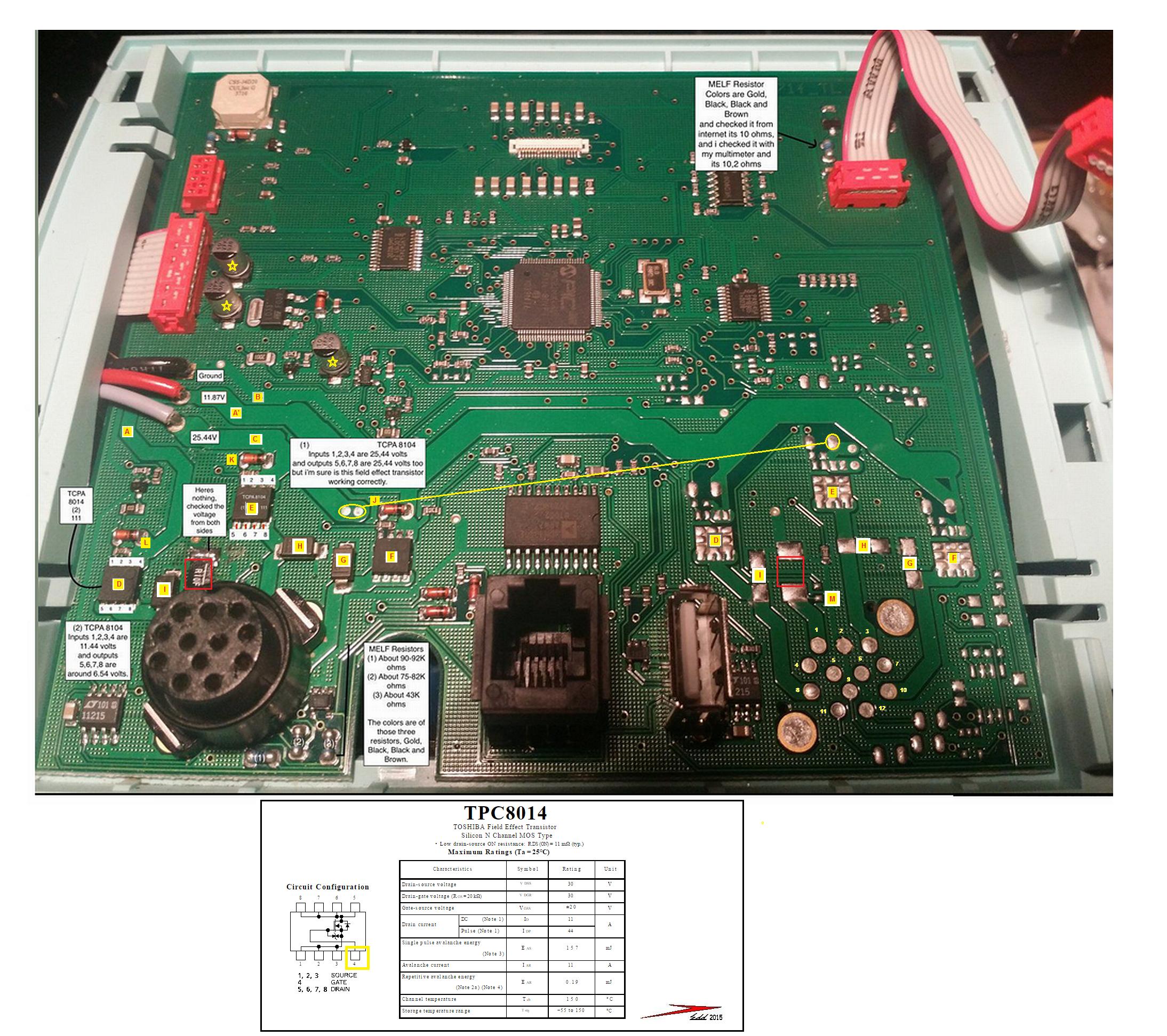
Now you need to confirm this for me, as I am potentially seeing 12 connections being on the soldering iron receptacle and I am
assigning YELLOW micro numbers to them.
A soldering iron and its wiring to its connector should logically be suspected as minimally needing two heavy wires to feed power
to the irons heating element.
There should be an equally hefty wire, to provide a safety ground from the shell of the irons case to the ground on the soldering station.
Lastly would be the need of two wires to connect to a thermal temperature sensing device.
That minimally requires the use of 5 wires.
If we now examine the connector on the right, I am seeing a heavy copper supply buss foil going from pin 10 to MOSFET switch F.
Likewise, I am seeing the same for pin 3 going up to MOSFET switch E.
The situation is being the same for pin 8 going up to MOSFET switch D.
On this machines capability to distinguish between different irons being plugged in, that just might be the pins arrangement/utilization on
each different unit, and whether it ends up being fed from either D,E or F switching Mosfet.
Now, how about that sub ohm metal film surface mount that you have CHANGED OUT . . . .and your measured it "has no power on it"
situation.
(I have its physical position being marked within a RED box in either half of the picture.)
I feel that WHICHEVER/ANY of the stations possible soldering irons options that you select, that the soldering irons connector pin will
be routed from connector pin 1, and have to pass thru that resistor and finally make its connection to the power ground buss
The low value resistor will be serving as an inline current shunt and its voltage sampling ACROSS it will be feed to the control electronics ,
using that fine little foil path that you can see marked as M.
(With it disappearing down into the multilayer board at that solder blob.)
Sooooooooo that would definitely be accounting for there being no metered voltage, when you tested across it.
PLUS, since it is so close to ground potential thru that low value of a resistor, it would only be a very-very feeble voltage. (The iron also
must be plugged in when testing for that voltage presence. )
A POTENTIAL SITUATION:
An accessory iron is plugged and an initial current is then sensed across the resistor and a proportional sampling voltage is created.
Control circuitry senses a QUITE higher current passage, so control circuitry responds in kind by thinking “ Whoaaaaaaa, this dude must
have the big 200 wat iron plugged in” so it responds by transitioning to 24VDC supply circuitry utilization.
Now, getting back to the receptacle, I can see pins 9, 11 and 12, with their fine foil connects as being used /for the thermal sensor connections.
That then only leaves connector pins 2,4,5,6 and 7 as providing the shell safety grounding for the iron.
I visually can't distinguish a floating connection, from ones connected to the foil ground plane on the photo, so fill us in with which ones
are being grounded, or if all of 5 of them are being grounded.
Checking your irons power plug, you might now see if only some pins, of a potential full 12, are coming out to connect to the stations receptacle.
Take an ohmmeter in hand to read resistances between different pins.
As I pointed out, on the blank connector photo, my assigned numbers have pin 1 as being the irons heaters ground connection and being one
heater element and having the other connection being either 10-3-or 8.
The thermal transitions of a 1K or 5K or 10 K resistance of a thermistor type of device might be read between 9-11 or 12.
Or the possibly of using a semiconductor sensor . . . not likely . . . so check for forward/reverse junction conduction and its Vf across its junction..
LOOKING AT THE BALANCE OF UNEXPLAINED PAGE MARKUPS:
The B was noting the ground buss and its HEFTY BLACK power supply wire to its left.
A and A prime are depicting the 12VDC buss and note that it goes right but also has aback route to feed down to switching MOSFET D.
C is the 24VDC power buss and the crossing YELLOW line and its two yellow circled lands are showing the hidden path for getting 24VDC
over to the switching MOSFET E.
At L K and J power supply points, we seem to have diode clamps to ground in the form of those MELF 1N400X “wannabe's”.
(They will have to fully grow up and grow leads out of their end caps to fulfill that possibility.)
Likewise after power passing thru those switching Mosfets D,E and F, their drains seem to have been clamped with diodes to ground at G, H and I
Should the power not incorporate slow switched off and on states, butinstead, be using variable pulse width modulation to the MOSFET gates,
tantalum electrolytics would be in order instead, but I don’t think I have ever seen any manufacturer using a black casing color for RECTANGULAR
surface mount units like these are.
A MUSING:
I wonder how long before those 3 YELLOW STARRED mini electrolytic cans, located up in the regulator circuitry develop bad ESR or leak ?
FINAL TROUBLESHOOTING NOTES:
And FINALLY, in looking at the switching MOSFETs, that item E seems to be a bad unit.
Ascertain which are being your soldering irons heating connections ,with consideration of Pin 1 as a common ground and 10-3-or 8, is being the
other heater connection and then figure if MOSFET E is being its power feed.
It seems like you just RANDOMLY assigned numbers to the pins of the TCPA8104's, since they are being backwards, with 1 being 4, etc. Pin 4 would
be the gate of MOSFET switch E.
Have POWER off and ohm out across D G and S of MOSFET E and see if it isn't dead shorted.
That would then account for full power on the iron with no temp regulation compensation.
BTW does the display of the temperature change as the iron initially heats up, or is that indication being fixed and is merely being the DESIRED
temperature level that you have set in ?
Note that your MOSFET D unit is exhibiting some degree of control from Source to Drain, but I don't know if it is being connected into a heating
element.
To do a dynamic test of MOSFET E, have a power down condition and suck/wick the solder from pin/lead 4, to float the gate, then heat that pin and slip
in a sliver of mica from an insulator to insulate and slightly lift that IC terminal up and thus ASSURE that lead is floating.
If you then power up, and read the same voltage from the power MOSFETS Source to Drain, it looks like a replacement is in order.
You seem to have overlooked MOSFET F in your testing, measure and pass its voltage readings on to us.
If in the end, you find that your sole soldering iron, if only having but one type, is being connected and controlled by Mosfet E, you might sub in a
good MOSFET from F or D positions to definitely confirm there being a faulty one now in E position.
A data sheet is placed just below the photo, giving the most dominant specs of the TCPA8104.
Thasssit . . . . I’m stopping to see what analyzed conditions and facts are actually being in agreement and any of your facts and answers to my questions , that you
can now feed back to us.
Your additionally marked up photo, is being placed just below:
Photo and its markup also available, off this site as:
http://i.imgur.com/VDziSoS.jpg
73’s de Edd