Learn about using UART with an ATmega168 and how it can be used to communicate with a PC!
So far we've learned about using the different peripherals found on the ATmega168. Now we will look at using UART and how it can be used to communicate with a PC!
Catch up on the rest of the ATmega168 series here:
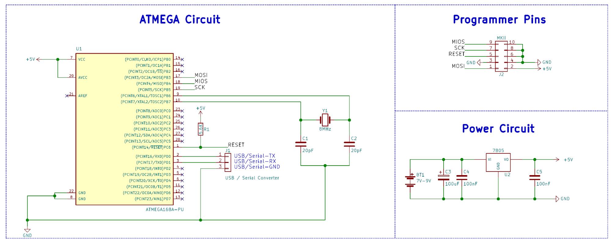
Schematic
Microcontroller Communication—What Is UART?
Microcontrollers often find themselves in specialized circuits with specific functions such as measurement, monitoring, and controlling. However, there are instances where connecting a microcontroller to a computer can be incredibly beneficial or even necessary (for example, device configuration). There are several ways this PC-Microcontroller communication can be achieved, including...
- Over Wi-Fi (such as the ESP8266 module)
- Ethernet
- USB
While these forms of communication may allow for high data-transfer rates, they are rather difficult to use, as well as being overkill.
Thankfully, there is one other type of communication that most microcontrollers come with called UART, which stands for Universal Asynchronous Receiver/Transmitter.
This is a simple serial connection that can be used for sending small amounts of data at low speeds and is incredibly simple to use and implement. What makes UART even handier is that there are USB-to-serial converters that can be used to allow a microcontroller to communicate with a PC via USB using a virtual COM port.
Serial Overview
Serial communication using microcontrollers and computers can include many different settings, including handshakes, parity, and stop bits. However, in this tutorial, we will look at the simplest form of serial communication, which is also one of the most common. So the first thing we need to look at is how serial data is sent. First, let’s look at the hardware!
A serial peripheral on a microcontroller in its simplest form is a glorified shift register that uses two separate I/O pins for sending data (TxDn) and receiving data (RxDn).
When data needs to be sent out from a device, it will put the data to be sent in its transmit shift register, and then clock the data out bit by bit until all the data has been transmitted. When data needs to be read, the receiver first needs to detect that some data is being received.
Once this condition has been met, the receiver shifts the data into a shift register. Once completed, the device can be read from the receive shift register and process the data in any way as it sees fit.
Simple block diagram of the UART module
The protocol itself that is used in UART modules (sometimes referred to as RS-232) contains options and extras that can help with data transmission/reception. The diagram below shows a typical UART transmission, which includes a start bit, the data itself, a parity bit, and stop bits.
Images taken from the ATmega168 datasheet
IDLE – If there are no transmissions occurring, the transmit line must be left at a logical 1 (5V, 3.3V etc)
Start bit – A falling edge on the UART line indicates that a transmission is about to begin
Data Bits – These are the actual bits of data we are sending, and the bits are sent lowest first (bit 0, bit 1 … bit 7)
Parity Bit – This optional bit can be used as a basic form of error checking by having a value that is equal to the exclusive-or (XOR) of all the bits combined
Stop bit – This is required to stop the transmission and is a logical 1. Sometimes, two stop bits can be used, but normally only one is used
UART on the ATmega
The UART module on the ATmega168 is very complex, as it allows for different modes of operation (including synchronous transmission), but we will be configuring the UART to use the most common setting that is suitable for 99% of UART-based projects.
Clock Source
The first thing we need to configure is the clock source for the UART module (this also configures the mode in which the UART operates). Since we will be using asynchronous transmission (clock is not transmitted, only data), we will use “normal asynchronous”. To do this, we set both UMSEL bits to 0 in the UCSRnC register.
Parity Bit and Stop Bit
Since most transmissions don’t require parity, we will disable this bit. To do this, we need to set both UPM bits to 0, which can be found in the UCSR register.
For the stop bit, we will only use one stop bit, which is done by clearing the USBS bit found in the UCSRnB register.
Data Size
The UART module is capable of sending data at different bit widths, but for most projects we will use 8-bit data sizes, since our microcontroller is an 8-bit device. To do this, we set the value of the UCSZ bits to 011 found in registers UCSRnB and UCSRnC.
Baud Rate
When talking about serial communication, baud rate typically refers to the number of data bits transmitted per second and can be thought of as a connection speed. Typical baud rates for serial communication include 9600, 115200, and 10417.
For our serial setup, we will use a baud rate of 9600 (a very common baud rate). The baud rate can be calculated using the formula found below, however, it is easier to use the tables found on page 163–165.
Since our ATmega168 is connected to an 8MHz oscillator, we can look at the table below to see what value we need to set our UBRR registers to.
For 9600 baud we will therefore use a value of 51. Note that your CLKDIV8 bit may be set, and if this is the case, then your baud rate may be eight times slower than you expect. If this is the case, try using a UBRR value of 12 instead and set the U2X0 bit on, or use a higher clock speed.
Enabling the Reception/Transmission
There are several enable bits we need to set and others that are optional. The first two bits that we need to enable are RXEN and TXEN, which enable the receiver and transmitter.
There are also two interrupt enable bits we can set, which means when our UART module finishes sending or receiving data, an interrupt will fire (useful for real-time applications).
Reading/Writing UART
Interestingly, the AVR UART peripheral uses the same I/O address for both the reception and transmission register. When the UART data register (UDRn) is written to, the data is sent to the UART transmitter shift register, and when reading from the UART data register, the data from the UART receiver is returned.
Some Useful Control Signals
One register, UCSR0A, can be helpful for determining the state of the UART module because it has several status bits.
- RXC0, bit 7, will be 1 if there is data in the receive buffer that needs reading
- TXC0, bit 6, will be 1 once a transmission has been completed
- UDRE0, bit 5, will be 1 if the transmit buffer is empty
- FE0, bit 4, warns of framing errors
- DOR0, bit 3, warns of Data OverRun (when too much data is received and the receive buffer is full)
- UPE0, bit 2, will be 1 when a parity error is detected on a received byte
A Simple UART Example
This example will look at creating an echo device, which will wait until a connected PC sends a byte down the UART line. Once detected, the AVR will then immediately send the same byte back to echo the message.
/*
 * AVR UART.c
 *
 * Created: 09/01/2018
 * Author : RobinLaptop
 */

// These are really useful macros that help to get rid of unreadable bit masking code
#define setBit(reg, bit) (reg = reg | (1 << bit))
#define clearBit(reg, bit) (reg = reg & ~(1 << bit))
#define toggleBit(reg, bit) (reg = reg ^ (1 << bit))
#define clearFlag(reg, bit) (reg = reg | (1 << bit))


#include <avr/io.h>


int main(void)
{
	// Initialize Registers

	// Configure register UCSRA
	setBit(UCSR0A, U2X0);				// Double the BRG speed (since I am using a 8MHz crystal which is divided by 8)
	clearBit(UCSR0A, MPCM0);			// Normal UART communication

	// Configure register UCSRB
	clearBit(UCSR0B, RXCIE0);			// We will not enable the receiver interrupt
	clearBit(UCSR0B, TXCIE0);			// We will not enable the transmitter interrupt
	clearBit(UCSR0B, UDRIE0);			// We will not enable the data register empty interrupt
	setBit(UCSR0B, RXEN0);				// Enable reception
	setBit(UCSR0B, TXEN0);				// Enable transmission
	clearBit(UCSR0B, UCSZ02);			// 8 bit character size

	// Configure register UCSRC
	clearBit(UCSR0C, UMSEL00);			// Normal Asynchronous Mode
	clearBit(UCSR0C, UMSEL01);
	clearBit(UCSR0C, UPM00);			// No Parity Bits
	clearBit(UCSR0C, UPM01);			// No Parity Bits
	clearBit(UCSR0C, USBS0);			// Use 1 stop bit
	setBit(UCSR0C, UCSZ01);				// 8 bit character size
	setBit(UCSR0C, UCSZ00);

	// Configure the baud rate register (this is a combination of both UBRR0L and UBRR0H)
	// Despite using an 8MHz crystal my Fosc is 1MHz since the CLK8DIV fuse bit is dividing the clock
	// by 8. When I try to change this fuse the AVR locks me out!

	UBRR0 = 12;

    while (1)
    {
		// Wait until data has been received
		while(!(UCSR0A & (1 << RXC0)));

		// Now send the same byte back
		UDR0 = UDR0;

		// Wait until the Data Transmit Register is empty
		while(!(UCSR0A & (1 << TXC0)));

	}
}