Maker Pro
Maker Pro

Any difference in out come? Bridge-Rectifiers

Maglatron

Jul 12, 2023
1,652
Joined
Jul 12, 2023
Messages
1,652
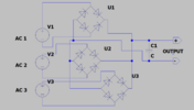
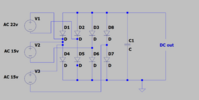
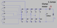
I wanted to know if there would be any difference in outcome with these two different designs of rectifier? The coils are not in phase or equal inductance or turns something tells me to do separate bridge rectifiers but I wanted a second opinion, cheers
Scott
 

Attachments

  • rectifier separate.png
    rectifier separate.png
    62.6 KB · Views: 7
  • rectifier.png
    rectifier.png
    104.9 KB · Views: 7

davenn

Moderator
Sep 5, 2009
14,300
Joined
Sep 5, 2009
Messages
14,300
WHY are you using 3 sources to obtain as single output ??
higher voltage ourputs from rectifiers are going to feen back into the lower voltage ones
This is a no-no
 

Maglatron

Jul 12, 2023
1,652
Joined
Jul 12, 2023
Messages
1,652
I have a wheel that turns 550 rpm, it has eight magnets attached on both sides and the coils are two on either side and the magnets pass coils in the actual version there are four power coils not three, and I represented them with voltage sources. I want to add up the voltage from the four coils and have one DC output! thanks for reply, how would you do it? I'll take photos when I can
 

Harald Kapp

Moderator
Moderator
Nov 17, 2011
13,779
Joined
Nov 17, 2011
Messages
13,779
higher voltage ourputs from rectifiers are going to feen back into the lower voltage ones
I'm sorry @davenn , but I have to disagree. This is not going to happen due to the backwards facing diodes in the rectifiers going to these lower voltage sources.
The lower voltage sources will contribute nothing to the output , again due the reverse polarized diodes. Only the highest voltage will contribute to the output:
1703149990895.png
The current through V1 is equal in magnitude (opposite sign due to the way it is "measured") to the current through the resistor. The current through V2 is null.

The scheme by @Maglatron will work only if the different voltage sources vary with time as would happen with the setup described in post #3. In that case the setup will work as a three phase rectifier.
 

Maglatron

Jul 12, 2023
1,652
Joined
Jul 12, 2023
Messages
1,652
WHY are you using 3 sources to obtain as single output ??
higher voltage ourputs from rectifiers are going to feen back into the lower voltage ones
This is a no-no
I'm sorry @davenn , but I have to disagree. This is not going to happen due to the backwards facing diodes in the rectifiers going to these lower voltage sources.
The lower voltage sources will contribute nothing to the output , again due the reverse polarized diodes. Only the highest voltage will contribute to the output:
View attachment 62226
The current through V1 is equal in magnitude (opposite sign due to the way it is "measured") to the current through the resistor. The current through V2 is null.

The scheme by @Maglatron will work only if the different voltage sources vary with time as would happen with the setup described in post #3. In that case the setup will work as a three phase rectifier.

so can you shed any light on the proper way to do this please? or is the way I'm doing this suffice which setup would you choose the separate diode bridge's or the this one thanks for the feedback !!
 

Attachments

  • rectifier.png
    rectifier.png
    104.9 KB · Views: 1

Maglatron

Jul 12, 2023
1,652
Joined
Jul 12, 2023
Messages
1,652
How do I wire it so that all of the voltage sources contribute what all the power coils have to offer, not just the highest voltage coil, so that in your example the 5volt source is doing nothing how do I make it so that it's contribution compounds with the 10volt source??
 
Last edited:

Maglatron

Jul 12, 2023
1,652
Joined
Jul 12, 2023
Messages
1,652
can I put the coils in parallel and rectify them all at once, in one go, with one bridge-rectifier?
 

Maglatron

Jul 12, 2023
1,652
Joined
Jul 12, 2023
Messages
1,652
I'll take a photo of it so you can see what you think then!
 

Harald Kapp

Moderator
Moderator
Nov 17, 2011
13,779
Joined
Nov 17, 2011
Messages
13,779
The voltages vary a little with time, but not much!
How is that possible? When a magnet induces voltage in a coil the voltage is definitely varying over time. Typically a sinusoidal signal.
Otherwise there is no need for rectifiers.
1703162812297.png
 

Maglatron

Jul 12, 2023
1,652
Joined
Jul 12, 2023
Messages
1,652
I think I didn't understand what you said. I thought you meant that the magnets are passing past the coils at different times the in the cycle of 1 revolution, the magnets at the top of the wheel and the bottom of the wheel magnets are passing the coils nearly at the same time like wise at 90 degree there is a coil on either side of the wheel where the magnets are passing the the coils nearly at the same time. I thought you meant the phase angle at different times but the phases practically match up so in your image, in real life the green and blue are almost matched in time!
 
Last edited:

Maglatron

Jul 12, 2023
1,652
Joined
Jul 12, 2023
Messages
1,652
So I just measured my parts on my machine there is a 38% increase in power. So I don't want to be sent off to woo woo part of the forum but... I now have a clamp meter, the battery to power it on, the Voltage is at 11.1volts. The Amps are 4.8, thats 53.28watts, the output is 65volts at 1.1amps, which equals 71.5watts, 71.5 - 53.28 = 18.22watts extra and 53.28 / 100 for 1 percent and then multiply by 71.5 and then so the increase in watts is 38.1% free power
 

Maglatron

Jul 12, 2023
1,652
Joined
Jul 12, 2023
Messages
1,652
Okey dokey couldn't have use of the camera today so I'm counting on it for tomorrow but for now I'm going to stick with stuff that happens in the real world for now, woo woo land is where I do NOT want to be! but I will upload pictures of what I've found and draw up a schematic and take photos of where I am measureing from at the points in the machine!
 
Last edited:

Harald Kapp

Moderator
Moderator
Nov 17, 2011
13,779
Joined
Nov 17, 2011
Messages
13,779
Use the one with the separate rectifiers (left image).
However, note that this will work in a useable way if the three voltages are at least similar if not equal in peak voltage. If not, this is what will happen:
Assuming V1 is higher than eitehr V2 or V3, then the capacitor C will be charged by V1 to V1peak-1.4 V (voltage drop across the diodes).
With V2 (or V3) lower than V1 these voltages will never achieve forward biasing in the respective rectifiers because the voltage across the capacitor reverse-biases the diodes. See the green line (current supplied by V1) vs the pink line (current not supplied by V2) in this image:
1703183712219.png

Only with V1 equal in amplitude to V2 both sources will contribute to the output:
1703183829251.png
 

Maglatron

Jul 12, 2023
1,652
Joined
Jul 12, 2023
Messages
1,652
And the BLDC motor that turns the wheel is a drone motor it's run by a ESC and the battery is at 11.1volts and the clamp meter around the red wire from the battery the amps read 4.8amps I read what you said about using the separate rectifiers and will do it when parts come! it'll be good to see the difference!
 

Attachments

  • diode bridge with clamp.png
    diode bridge with clamp.png
    137 KB · Views: 3
Last edited:

Maglatron

Jul 12, 2023
1,652
Joined
Jul 12, 2023
Messages
1,652
the waves are like radio waves because when you tune in the middle of two stations at just the right point both stations will play even louder than one on it's own one wave can piggy back the other wave, not sure you have heard of this before! hence why I staggerd the magnets by a third on one side to the other! try it yourself with an old fm radio with a knob tuner!
 
Last edited:

Martaine2005

May 12, 2015
4,967
Joined
May 12, 2015
Messages
4,967
As already stated, you can’t get free energy. If you could, the government would kill you!.
Think of Watts going in and Watts coming out minus the losses in resistance, capacitance and inductance. A loss is, less than you put in!.
People get confused with voltage and current. “I can make 24v from 12V”. Sure, you can, at a loss. You can have for example, 12V at 15 Amps or 6V at 30A. Ohms law doesn’t play games, especially free games.
 
Top