Sparkymark
- Feb 16, 2024
- 42
- Joined
- Feb 16, 2024
- Messages
- 42
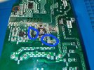
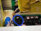
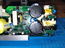
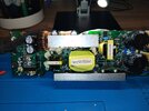
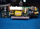
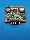
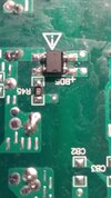
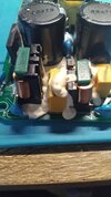
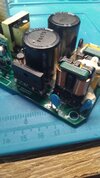
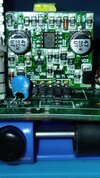
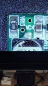
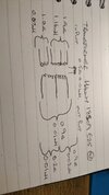
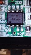
Hi all, I am a qualified electrician and recently decided to get into electronics. I have been working on a power supply board for a naim mu so 2 all in one speaker. It had 5v standby and I was checking voltages and accidentally shorted positive side of bridge rectifier to heatsink. Obviously went bang. Now when I plug it in it blows a single 400v 4.7uf capacitor and shorts a diode just before it. There is also a smaller circuit board upright on the main board with 2 wires running to it from the transformer, I'm guessing this might be something to do with PFC but not sure. There is a resistor on there that has also got a damaged pad but resistor is still intact and attached to what remains of the pad. Any ideas what could be the issue. I'm thinking maybe shorted at the little board so sending high voltage back thru negative side of capacitor. Any advice very much appreciated. Thanks for reading.
I will try to get some pics for clarity.
I will try to get some pics for clarity.