Maker Pro
Maker Pro

Capacitor explodes on PSU

Martaine2005

May 12, 2015
4,963
Joined
May 12, 2015
Messages
4,963
There will be one or possibly two components shorted.
Finding them is usually quite straightforward given the symptoms. Your ability or inability to fault find is important here.
 

kellys_eye

Jun 25, 2010
6,514
Joined
Jun 25, 2010
Messages
6,514
Not sure what your point is, as long as the picture shows what I'm talking about I don't think it matters too much does it.
Pictures of areas of the board YOU think have issues may not show problems elsewhere that you might have missed. Equally, close-ups of individual components don't give the viewer any context to consider what that component may be and how it interacts with parts associated (around) with it.

Pictures that show 'as much as possible' consistent with sufficient resolution for the viewer to pan/zoom around it can often reveal vital information. Otherwise you might end up having to post multiple images in order for the view to 'build a complete picture' of what is going on.

Just my ha'penny.
 

StanUlam

Mar 1, 2024
3
Joined
Mar 1, 2024
Messages
3
One thing nobody seems to have mentioned is that the exploding capacitor could have left a trail of metal across a couple of of PCB lands and that is what could be shorting out rather than a component.
 

Sparkymark

Feb 16, 2024
42
Joined
Feb 16, 2024
Messages
42
That device is certainly a triac. But what is it controlling?
OK, I have removed the heatsink with the triac and the 2 mosfets on it. I have reinstated the 2 opto's, another mosfet which has just arrived as I broke a leg whilst testing. And I have put a new diode and capacitor on the board. Powered on without the heatsink components and all fine, no explosions.

As for the triac, there is 240v ac going to the small board on pin 1 and the second pin off the board has a trace going to A1 of the triac. A2 of the triac has a trace going back to the centre tap of the 2 main filter caps. Pin 2 and 3 of the board both have the wire that goes to the transformer and the gate of the triac goes to pin 4 of the board. Not sure if any of that will make any sense to you but that's all I see. Thanks
 
Last edited:

Sparkymark

Feb 16, 2024
42
Joined
Feb 16, 2024
Messages
42
Pictures that show 'as much as possible' consistent with sufficient resolution for the viewer to pan/zoom around it can often reveal vital information. Otherwise you might end up having to post multiple images in order for the view to 'build a complete picture' of what is going on.

Just my haha'penny.
Thanks for the input, I'll bear that in mind. Thankyou
 

kellys_eye

Jun 25, 2010
6,514
Joined
Jun 25, 2010
Messages
6,514
Not sure if any of that will make any sense to you but that's all I see.
Nope, me neither!

This is where another pic with the appropriate annotations on it would make a big difference. I also find it confusing to have to scroll back 'pages' to reference the 'small board' so please try to keep the posts relevant by including the information we need instead of us having to seek it.
 

Sparkymark

Feb 16, 2024
42
Joined
Feb 16, 2024
Messages
42
OK, so I replaced the triac. Reinstalled all other components and no bangs or explosions. Happy days. Still no standby and upon further inspection found that chip LD7750RGR PWM controller has an 8 ohm short between pin 2 (comp) and pin 4 (gnd). Am I correct to assume this is not right?
 

Martaine2005

May 12, 2015
4,963
Joined
May 12, 2015
Messages
4,963
Not being a @&ck but may be useful to others if you link to it rather than us copy/ pasting or worse, typing.
Difficult to say without the data sheet, 8 Ohms isn’t really a short. It also depends on the circuitry around that chip.
 

Sparkymark

Feb 16, 2024
42
Joined
Feb 16, 2024
Messages
42
Not being a @&ck but may be useful to others if you link to it rather than us copy/ pasting or worse, typing.
Difficult to say without the data sheet, 8 Ohms isn’t really a short. It also depends on the circuitry around that chip.
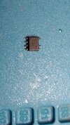
Sorry don't know what you mean link to it. I removed the chip and tested between the pins. The only other 2 components were pins 3 and 4 of an opto which I removed and tested OK and a ceramic cap which once removed tested OK. I'll attach a pic of the chip. I have a new phone and can't make it screenshot so can't attach pic of datasheet and techy enough to know how to link it. Sorry, I'll try harder in future lol.
 

Attachments

  • 1709930388583624990474499844509.jpg
    1709930388583624990474499844509.jpg
    273.7 KB · Views: 4

Sparkymark

Feb 16, 2024
42
Joined
Feb 16, 2024
Messages
42
So I've done a diode check between pin2 comp and pin 4 gnd. Getting a reading of 0.016 in both directions. Looking at the block diagram there is 2 diodes and 2 resistors. Can anyone confirm my findings.Datasheet is on previous post
 

Sparkymark

Feb 16, 2024
42
Joined
Feb 16, 2024
Messages
42
Well I've ordered some new chips anyway so will compare readings on a new one. Thanks for the help
 
Last edited by a moderator:

Harald Kapp

Moderator
Moderator
Nov 17, 2011
13,769
Joined
Nov 17, 2011
Messages
13,769
that chip LD7750RGR PWM controller has an 8 ohm short between pin 2 (comp) and pin 4 (gnd).
Usually you can't measure a complex chip like this with a multimeter.
This chip has ESD input protection on the pins. This protection is usually done by diodes from the pin to Vcc and GND like so (although the datasheet doesn't state this explicitly for this chip). Your measurement may simply show the forward biased pn-junction of the protection diode(s).
 

Sparkymark

Feb 16, 2024
42
Joined
Feb 16, 2024
Messages
42
Usually you can't measure a complex chip like this with a multimeter.
This chip has ESD input protection on the pins. This protection is usually done by diodes from the pin to Vcc and GND like so (although the datasheet doesn't state this explicitly for this chip). Your measurement may simply show the forward biased pn-junction of the protection diode(s).
Thank you for the reply, and thanks for the information. Its just that I looked at the block diagram from the datasheet and it shows 2 diodes on pin 2 comp and if I'm getting a diode reading of 0.016 between comp and gnd in both directions, would that be a possible fault.


Harald Kapp

Moderator
Moderator
Nov 17, 2011
13,769
Joined
Nov 17, 2011
Messages
13,769
if I'm getting a diode reading of 0.016 between comp and gnd in both directions, would that be a possible fault.
Very likely. A diode reads something like 600 - 700 on most multimeters - that's the voltage drop across the pn-junction.
 
Top