Sorry if I seem clueless but just need to understand.
There are plenty of online reference articles that explain the workings of SMPS devices and some that offer advice on repairing them. Your current knowledge is lacking and your pictures/descriptions don't help either.
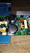
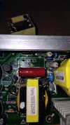
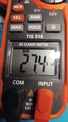
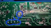
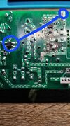
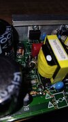
From FIRST PRINCIPLES - the power comes in via a fuse and filter(s) to a bridge rectifier and smoothing capacitor arrangement when the DC that is required to be 'chopped' is derived. If you isolate EVERYTHING after the smoothing capacitors you should be able to measure around 310V DC across those capacitors.
Anything that 'explodes' after this 310V is delivered is as a result of the main switching component(s) being shorted.
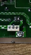
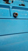
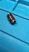
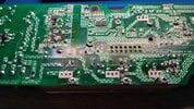
The devices on the big heatsink seem to be only 'plugged in' to the circuit board - are they IN (and soldered extremely badly) or are they OUT?
Lastly, do you know what 'landscape' means (in terms of photos)?

")