Also should I go ahead and desolder PIN 11 of 4127? and if so.. what should I look for after I desolder PIN 11..
NO . . . . no need to float / desolder pin 11 that was being related to your initially only finding 1.8 VDC on it.
Your retest has now shown that the 4117 is NOT severely loading down your input power. . .and is actualluy pulling ~
~ 300 mw.
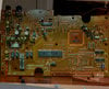
BATTERY POWERED ON:
PIN 1 : 9.04V
PIN 2 : 8.36V
BATTERY POWERED OFF:
PIN 1 : 9.25V
Can you now do my earlier test of going into AC metering mode in 1 VAC or less range and measure with meter neg to ground and red meter lead to
4127 and replicate the earlier procedure found in post # 24. Repetitively key in and then stop a note and the meter should respond accordingly.
Therewith, we are wanting to know if there actually is a note being created back at the uPs output and then showing up at the audio input of the 4127.
If being so, we will then have to further evaluate the units 4127 situation.
Sir I have completed your test of pressing a key and measuring the voltage.
keyboard was battery powered, turned ON, volume at max position.
With my black lead on ground and my red lead on LA4127 PIN 6 there was no voltage change when key was pressed or not. It stayed at 0 VAC
With my black lead on ground and my red lead on LA4127 PIN 15 there was no voltage change when key was pressed or not. It stayed at 0 VAC.
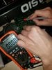
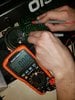
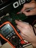
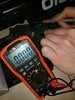
I wasn't sure if I was selecting the range properly so I've attached a picture.
I also did the same test of having someone press a key while measuring the voltage on DC mode just to see if it made a difference and it did not.... both pin 6 and pin 15 stayed at 0vdc, regardless if a key was pressed or not...
Although there definitely was a lot of audible static coming from the speakers when my red lead was on 6 or 15 I noted.
I also did the test with my black lead on pin5 and than tested pin 6 and pin 15 with someone pressing the keys, no voltage was measured at all. I did both AC and DC....
But my conclusion was that there was no change when the key was being pressed... all the reading were at 0 volts....
I've attached a picture and maybe let me know if my meter was on the correct setting.
Attachments
Last edited: