Maker Pro
Maker Pro

I'm Back- sort of

SparkyCal

Mar 11, 2020
849
Joined
Mar 11, 2020
Messages
849
Hi Bertus and my other friends here. You may recall that after an almost daily presence on this forum, I packed it in with my interest in electronics.

However, I am revisiting this interest and have assembled a portable, multi shelf unit on wheels, that houses a scaled down version of my electronics equipment.

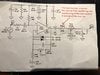
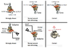
My interest remains in building distortion or overdrive stomp boxes for my guitar playing. My new goal is to build a stomp box that allows me to swap in different distortion producing components. The idea is to have a working stomp box that allows me to experiment with different diodes, LEDs etc, to see what kind of tone and distortion I can get.

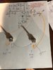
I found such a project online, and have provided a link to it below. I confess to having tried to build it, and it did not work. So, now I am thinking I should go back to basics and breadboard it, with the help of the kind people on this forum. Please let me know if you're willing to help me along the way, if and certainly when, I get stuck.

I promise to post good pictures of where I am at along the way. Have a look at this link , if you have time. I will let you know when I take my first steps.

Thank-you all! I hope you have all been keeping safe during this pandemic!


I suspect there may be better ways of dong this type of thing, but this is the only video I found that dealt with this approach.
 

SparkyCal

Mar 11, 2020
849
Joined
Mar 11, 2020
Messages
849
Hi Bertus. I have seen that schematic in the past. I consider it the gold star of such schematics in that it provides for complete flexibility and the toggling of configurations. In many ways, it is far beyond my capabilities, including he fact that I would need all kinds of different diodes etc. moreover, despite its rich design, it remains confined by the diode config that the designer chose. I would really like to try things on there fly, and that's why the two alligator clips that are entailed in the link I posted, appeals to me. Maybe, if I get better at this stuff, I can try that project in. the future. thank-you. and nice seeing that you are still part of this forum. Great!!!!
 

SparkyCal

Mar 11, 2020
849
Joined
Mar 11, 2020
Messages
849
Just started breadboarding and already I have a question (I'm rusty ;-))

In the attached picture, you will see that I drew a dotted line around a component of the circuit ( the input jack of the pedal). Does that dotted area refer to the sleeve or the tip of the jack? I think it is the sleeve but am not sure.

Thank-you
 

Attachments

  • Image 2021-05-11 at 4.16 PM.jpg
    Image 2021-05-11 at 4.16 PM.jpg
    64 KB · Views: 15

bertus

Moderator
Nov 8, 2019
3,349
Joined
Nov 8, 2019
Messages
3,349
Hello,

Are you sure the circuit uses a TDA2030?
The TDA 2030 is a 14 Watt power amplifier.

Bertus
 

Attachments

  • TDA2030.pdf
    546 KB · Views: 2

SparkyCal

Mar 11, 2020
849
Joined
Mar 11, 2020
Messages
849
Perhaps already the first major snag. I don't have a TDA2030. I thought it was simply an op amp. I have several different types of op amps, from the days when I was here working on this stuff. I thought I would simply use one of the op amps I have, understanding that I would have to map the pins. So, the op amp I was planning to use is the UA741CP. Does that mean that my approach won't work?
 

Audioguru

Sep 24, 2016
3,656
Joined
Sep 24, 2016
Messages
3,656
The circuit you found id completely useless and is wrong with a obsolete TDA2030 power amplifier that has a minimum of 12V for its supply so it will not work with a 9V battery that drops to 6V and it will not work with an old 741 opamp with different pins numbers since the circuit is completely wrong. The distortion in the video sounds awful.
 

SparkyCal

Mar 11, 2020
849
Joined
Mar 11, 2020
Messages
849
Hi Audioguru. well, this remind me of old times (in a good way ;-)). I recall you had discerning tastes on what distortion should sound like.

For the record, the distortion I use professionally, is a Fulton OCD- it's used by many of the greats; the Eagles being one example.

I'm trying to get back into making these stomp boxes, and trying to use parts I already have. I have two goals at the moment:

1. To get back into electronics by building a stomp box with parts I already have. I also have a ton of the 488D op Amps (which I know you're not a fan of). It's not about the sound right now- It's just about building a box successfully.

2. I was hoping to buoy,somethign that I can swap diodes in and out of, to experiment.

Maybe I should tackle goal 1 first.

-Back to the drawing board. I'll need to find a schematic that I can build, using wither the 741CP or the 4885Ds (which is what I have).
 

SparkyCal

Mar 11, 2020
849
Joined
Mar 11, 2020
Messages
849
I think I'm going to re-do this one, just to get back into it. You will recognize this because you folks helped me understand it, and you made notes to it.
 

Attachments

  • schematic.jpg
    schematic.jpg
    76.1 KB · Views: 13

Audioguru

Sep 24, 2016
3,656
Joined
Sep 24, 2016
Messages
3,656
Most Fuzz or Overdrive distortion is the amplifier clipping or the diodes clipping the amplitude of the signal. Most clipping is symmetrical so the top and bottom of the waveform are equally limited at the maximum amplitude. Smooth signals end up as squarewaves.
Symmetrical clipping produces odd numbered harmonics that are not musical. Some distortion pedal circuits also produce non-symmetrical even harmonics that are musical because they are octaves apart.

The very old "Fuzz Face" circuit uses germanium transistors and produces odd and even harmonics. Here are the waveforms of Fuzz Face:
 

Attachments

  • fuzz face waveforms.png
    fuzz face waveforms.png
    23.9 KB · Views: 6

SparkyCal

Mar 11, 2020
849
Joined
Mar 11, 2020
Messages
849
Thanks Audioguru and Harald...nice to hear from you both.

I know the fuzz sound was really big in the Hendrix days, and is still used today. I have used that particular sound in the past, but sparingly. Thanks for explaining the electronics behind it in terms of the waveform shapes and characteristics.

I guess my ultimate hope is to build something that, combined with a certain guitar whose tones, volumes and pickups are set to a certain way, creates a signature sound that is unique to me. That's a huge stretch, I know, and I may never get there. But with all the different variables at play: the guitar, the guitar set up, the components used in the stomp box (op amps, diodes etc), maybe it will someday magically happen.

Truthfully, for me to remain interested in something, I have to attach a goal to it; even if it is aspirational.

Now, back to building that old circuit. I just finished soldering in that new resistor that I believe Audiioguru may have suggested ( the 270R).

By the way; I'm sure I may have asked this in the past, but what op amp do you folks feel is modern and worth using in a pedal?
 

SparkyCal

Mar 11, 2020
849
Joined
Mar 11, 2020
Messages
849
Ok..this question is simply based on my being out of touch with this stuff, and my b=-needing to brush up. The circuit now calls for a 100K pentetiomter (right after the 270R) resistor. The potentieimter has three prongs (Left , Middle and Right). I am confused as to which one goes where, because some web pages I saw, seem contradictory. So, in the context of the schematic , which lead goes to ground, which one goes out and which is connected to the 270 R resistor? Here is my guess:

If the three prongs are facing me, the left one goes to ground, the middle one goes to the Out (jack) and the right goes to the 270R resistor. Correct?

Thank-you
 

Attachments

  • schematic.jpg
    schematic.jpg
    76.1 KB · Views: 8

bertus

Moderator
Nov 8, 2019
3,349
Joined
Nov 8, 2019
Messages
3,349
Hello,

Have a look at this "drawing":
sparky output circuit.jpg
Don´t mind the values, the drawing is just for the idea how to connect.

bertus
 

Harald Kapp

Moderator
Moderator
Nov 17, 2011
13,758
Joined
Nov 17, 2011
Messages
13,758
The center tap is the one with the arrow in the schematic. Literally shown in the center of the potentiometer.
Left and right are interchangeable for linear potentiometers. How you connect them depends on the effect you want to create. Take for example the gain potentiometer.
Usually you want low gain with the potentiometer turned counterclockwise and high gain with the potentiometer turned clockwise. In your circuit thus translates to:
low gain: potentiometer's resistance is low
high gain: potentiometer's resistance is high
(Note: this depends really on the circuit, in other circuits this may be reversed).

For reference the gain potentiometer and your circuit (in this circuit one end of the potentiometer is connected to the wiper, making it a variable resistor):
upload_2021-5-12_19-19-13.png
To operate as described in text above, you'd connect the right pin with center, thus the resistance will e low when turned left (because the wiper is then near the left pin) and resistance will be high when turned right (because the wiper will then be near the right pin). You can (imho easily) visualize this by thinking of the arrow as movin physically along the resistor from left to right.

It is a tad different (don't worry, not much) with the volume potentiometer. Again for reference:
upload_2021-5-12_19-25-31.png
Volume will be high when the wiper is near the input (wire coming from top left) and volume will be low with the wiper being near ground (bottom). So this defines where left and right pin of the potentiometer need to be connected.

Another point to consider: For audio applications the volume potentiometer is usually of the logarithmic type to better match the sensitivity of the human ear to changes in sound level. Read e.g. this discussion. Left and right (or clockwise / counterclockwise) apply just the same.
In your application the gain potentiometer may possibly be linear (for the effect) but the volume potentiometer is probably meant to be logarithmic.
 

Audioguru

Sep 24, 2016
3,656
Joined
Sep 24, 2016
Messages
3,656
I believe that the potentiometers are shown wrongly.
The tone control cuts highs and should be clockwise for maximum highs.
The volume control should be clockwise for most loudness.
 

Attachments

  • tone and volume controls.png
    tone and volume controls.png
    194.8 KB · Views: 6

SparkyCal

Mar 11, 2020
849
Joined
Mar 11, 2020
Messages
849
I think I'm confused. Here is how I did it, after changing it around a few times, after having read the various explanations.

O
| | |
L M R
Above is a diagram of an Ariel view of the potentiometer, and it's prongs L = Left prong. M =- Middle prong R = right prong


10 K Tone:
Prong Left. goes to 270R resistor
Prong Middle goes to C29 (22nf capacitor) and then to ground
Prong Right- goes to prong Left of 100K Volume petentiometer

100K Volume

Prong Left. takes wire from prong Right of 10 K Tone
Prong Middle goes to Out
Prong Right- goes to Ground
 

Audioguru

Sep 24, 2016
3,656
Joined
Sep 24, 2016
Messages
3,656
We do not see your potentiometers so we do not know if the knob points towards you or points away from you.
Simply pick a pair of my sketches and paste them into Microsoft Paint program.

Use an ohm-meter to determine that the volume control slider (middle prong) connected to ground when the volume control is turned down.
 

Attachments

  • volume control.png
    volume control.png
    40.9 KB · Views: 3

SparkyCal

Mar 11, 2020
849
Joined
Mar 11, 2020
Messages
849
Sorry. I don't use Windows. I'm on a Mac. But this diagram should illustrate where I am at. This is my current wiring . The pots shown are not the actual pots, so ignore their values. They are just there as a proper to show the prongs and where they are wired to presently
 

Attachments

  • IMG_5056.jpg
    IMG_5056.jpg
    72.4 KB · Views: 5
Top