Looking at the supplied circuit diagram, it's quite a complex arrangement.
Normally one would expect to see differing outputs dependant on the secondary taps however this "appears" to have some primary input control.
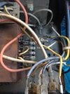
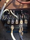
Clearly the four wires in photo 1780 would go to 4 of the 5 terminals on the transformer but which and in which order?
One could possibly identify which 4 terminals were used to begin with as one would be a lot dirtier than the other 4 and possibly one could verify the four used by the marks left by the spade terminals.
Then I see one of the white conductors apparently disconnected as well but assume that one to have been disconnected from the switch.
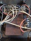
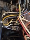
Lay of the wiring in it's "normal" state usually tells a lot.
Order of the connections is important and without a "full" circuit diagram, i.e. that of the transformer windings, one could not be certain.
Perhaps knowing the switching sequence might be of assistance but then again still no transformer diagram.
Maybe show a photo of the charger and display on facebook or similar with an appeal for an "internal workings shot" might help.