Use an Arduino and a motion sensor to make a camera motion activated.
It may be too early for Christmas-themed projects, but I'm sure you can find a use for this PIR motion-activated camera system anytime of the year!
Why?
When I was a little kid, my dad used to set up a video camera in the living room on Christmas Eve night, right near the milk and cookies. The next morning, after tearing through my presents, my family and I would sit down and scroll through the footage to see if we caught anything. To our surprise, Saint Nick walked right past the camera—but we didn't get a shot of his face!
Since my childhood, I've tried to stay up late in order to catch him myself. Last year, I figured I would beat the fat man at his own game! With a few components and my trusty DSLR, I found a great
All About Circuits article and modeled my "Santa Cam" after it. I found my nearest spare Debra-head and strapped on the components and used her as a scarecrow (act natural, nothing to see here)!
Getting ready to make our connections
How Does the PIR Motion-Activated Camera System Work?
First, we need to understand how
my camera works. Your camera may be different, so be sure double check your manual before moving forward. My camera is a
Canon EOS Rebel T3i with a 2.5mm TRS (tip, ring, sleeve) remote shutter jack. It uses a common auxiliary TRS cable (3.5mm), like the one you use to plug your phone into your car to play music. I had an extra cable lying around but the connector was too big for my camera, so I had to buy a
3.5mm female–to–2.5mm male adapter.
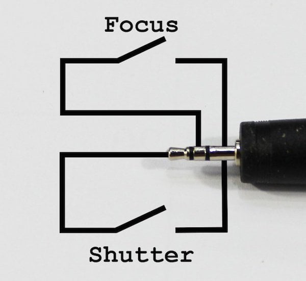
In a typical setup like mine, you can control the shutter or focus separately by shorting either of the corresponding leads to ground. On my cable, the tip (T) controls the shutter, the ring (R) controls the focus, and the sleeve (S) is ground. By shorting the tip or ring to the sleeve, we can activate one of these two functions.
How my camera shutter control functions
For this setup, we can control both the shutter and the focus by shorting the tip terminal to ground so the camera to auto-focus if done long enough. You can use the focus conductor if you'd like to control the focus separately from the shutter, in case you'd like to focus the camera without taking a photo.
With the tip shorted to ground, the camera will auto-focus and take a picture, and then we can disconnect the tip terminal from ground. Instead of using an unnecessary relay to do this, we can connect our camera directly to the Arduino. This also protects the camera from potentially harmful voltages.
Be careful constructing your circuit: make sure both devices are powered off connections and double check the circuit before turning the power back on. Cut the opposite end of the aux cable and strip the individual wires. Connect the ground conductor on the cable to one of the Arduino's ground pins so both devices share a common reference. If you are unsure of the wire connections, check for electrical continuity with a multimeter.
Arduino PIR Motion-Sensor Camera Circuit Diagram
The shutter terminal is plugged into digital pin 10 but we'll need to insert a diode between the shutter terminal and pin 10 in order to protect the circuitry inside the camera. This is to prevent the flow of current in one direction.
We'll configure our diode with the cathode pointing toward pin 10. This allows the shutter functionality to be activated by a logic-LOW signal. Then the logic HIGH signal from the Arduino won't interfere with the circuitry in the camera because the diode ensures that a significant amount of current can't flow from the Arduino pin to the camera.
I used a basic PIR sensor for my setup, but there are other models that allow you to adjust range and sensitivity if you prefer versatility. There are three wires: one for power, another for ground, and the last for signal.
Power and ground are connected to the appropriate pins on the Arduino, and the signal pin is connected to digital pin 7. When the PIR motion sensor detects motion, it sends a logic HIGH signal (5 V) to the Arduino. When this logic HIGH is detected by the Arduino, it pulls the shutter pin LOW and keeps it LOW long enough for the camera to focus and snap a picture, and then returns it to logic HIGH.
if(val == HIGH)
{
digitalWrite(shutterPin, LOW);     // set the shutter pin LOW to short the terminal to ground and activate the shutter
delay(3000);     //delay for camera to focus and take a picture
digitalWrite(shutterPin, HIGH);     // set the shutter pin HIGH in preparation for the next photo
}
That's it! Now you can catch the fat man in the act, or that pesky roommate stealing from your side of the pantry.
Other PIR Motion Sensor Tutorials
Other MIT-i Innovations