Maker Pro
Maker Pro

Dell Harmon Kardon Hk395 pc speakers

Status
Not open for further replies.

PtrkLnk

Jan 20, 2012
26
Joined
Jan 20, 2012
Messages
26
21gLB4yrw1L._SL500_AA300_.jpg


These speakers were plugged into my computer when it had a large surge come in through the internet plug. The computer survived just fine, but the speakers did not.

there is a knob on the front of the one speaker that is used to turn them on and off, and adjust the volume. The little green light on that speaker still lights up when you turn it on, but no sound will come out of the speakers even if I turn both the PC and speaker volume all the way up. It also does not make the pop sound that it used to when you turn it on. I checked the sound in cable and it is just fine.

I am sure that the surge came in from the sound in cord not the power cord. I have taken it apart and there is nothing visually wrong with any thing in there. I will take some pictures of the inside and post them in a few minutes.
 

CocaCola

Apr 7, 2012
3,635
Joined
Apr 7, 2012
Messages
3,635
Pull the pc board and get some pictures of the back of it so we can see if there are any obvious signs of damage there...

And the obvious question, you did check the fuse next to the big yellow wires right?
 

PtrkLnk

Jan 20, 2012
26
Joined
Jan 20, 2012
Messages
26
Yes I did check that fuse, and it is fine.

Here are some pictures of the back of the main PCB, and the little PCB were the inputs are

IMG_3131.JPG

IMG_3136.JPG
 

CocaCola

Apr 7, 2012
3,635
Joined
Apr 7, 2012
Messages
3,635
What are the two 14 pin ICs? Can you read a part number?

If your theory that the surge came though the line in, those ICs and surrounding components would have likely taken the blunt of it...

I don't like the fact that you are not getting the start up pop of the amp though, that will generally happen even with no input and might point towards that chip being toast or never getting the startup logic if it has some sort of sleep mode... So maybe the part number of the amp chip, the upright chip attached to the heatsink would help...
 

KrisBlueNZ

Sadly passed away in 2015
Nov 28, 2011
8,393
Joined
Nov 28, 2011
Messages
8,393
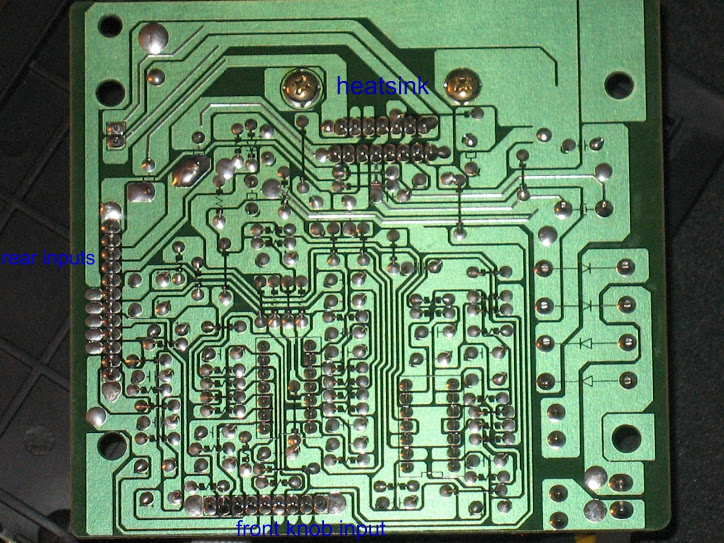
From the track connections underneath, I think the output IC is an STA540. This is a rather nice quad audio amplifier. Two channels are being used in bridge configuration for the woofer, and the other two are used in single-ended configuration for the two satellite speakers.
First check for the DC supply voltage across the big electrolytic. The STA540 expects 8~22V (it will probably be near the top end of that range, for maximum output power).
Assuming that's present, the IC has three control/diagnostic pins you can check before ordering a replacement (Digikey have them).
Pin 6 is called "SVR" and is connected through C30 to ground. It should probably have about half the main supply voltage on it, though this isn't entirely clear from the data sheet. If the voltage here is much less than half the main supply voltage, C30 might be damaged.
Pin 7 is the standby input. It should normally be driven with a voltage, typically 5V, through a current limiting resistor. Your photo seems to show it connected to the main positive supply, which would be a design error according to the data sheet. It's not clear whether the pin is connected to the supply rail, or not connected at all. If it's not connected, the data sheet doesn't say what the device will do. Can you measure the voltage on that pin?
Pin 10 is a diagnostic output pin. It's an open collector output that closes to ground if there's an output short or thermal shutdown occurs. You can measure it with a digital multimeter on resistance or diode range, with positive probe to pin 10 and negative probe to ground. If it indicates anything other than a high resistance or open circuit, the STA540 is telling you that there's something wrong.
The STA540 includes anti-thump circuitry so it should not make any noise when you turn it on and off. It might actually be working, but you can't hear any sound from it. You can try injecting a signal on pins 4 and 5 (which are connected together) (the signal should be audible on the woofer) or pins 11 and 12 (should be audible on the satellite speakers).
If the output IC is dead and gone, it should be worth replacing it, but check the other ICs too.
Can you tell us more about the nature of the "large surge"?
edit: Sparkfun sell a kit that uses the STA540, and they sell the IC separately too, for USD 2.95.
 
Last edited:

PtrkLnk

Jan 20, 2012
26
Joined
Jan 20, 2012
Messages
26
The large surge was a lightning strike. Every thing including the speakers was on a surge strip, but most of the lightning came in through the phone, internet, and TV cords. Although the computer is just fine, there is a lot of scorch marks on the inside where the back inputs/outputs are. I think the lightning must have jumped around and ended up going out through the speaker cord.


It is kind of hard to see the part number on the IC that is on the heat sink, but I will try to get it written down.
 

PtrkLnk

Jan 20, 2012
26
Joined
Jan 20, 2012
Messages
26
the two little IC's are the same, they say on them

STA LM324N
699EC0309
Malaysia

the bigger one on the heat sink is

STA TDA7375A
6889070332
Singapore
 

CocaCola

Apr 7, 2012
3,635
Joined
Apr 7, 2012
Messages
3,635
It looks very similar but I do not think it is the same because it says 2x37 not 4x13.

Read the next paragraph... ;)

And note that you can NEVER trust a manufacture (of the consumer product) to give you solid performance ratings of an audio amplifier... They all like to brag about how much output it can produce under 'perfect' circumstances not what it will do in the real world... Example they never tell you those ratings where achieved in a deep freezer with a constant flow of coolant over the chips, or some other 'perfect' scenario they implemented...

BTW before just jumping in to replace chips you might want to spend some time reading the datasheet and doing things like KrisBlueNZ suggested, you might be able to determine the fault or narrow it down...

But, I'm pretty confident if you replace all three of those chips that it will work again, as they are really the heart and sole of the whole circuit... BUT, before you do that double check the transformers output, I know you said the LED lights and thus I would assume the transformer is functional but it's best to test before you commit to swapping out parts...
 
Last edited:

KrisBlueNZ

Sadly passed away in 2015
Nov 28, 2011
8,393
Joined
Nov 28, 2011
Messages
8,393
You're right, it's not the STA540. A tab is clearly visible in the photo, and the STA540 doesn't have a tab - it's in a "clipwatt15" package that is held to the heatsink with a clip.
The TDA7375A seems to be indistinguishable electrically, and has the tab that you want. The data sheets are almost identical; the STA540 data sheet looks like the TDA7375A data sheet with some tidying up, some extra information added, and changes due to the package differences. I think the two devices probably have the same silicon inside them. Pinouts are identical. Differences I noticed are:
TDA7375A has lower maximum supply voltage (18V vs. 22V) and lower maximum output power specifications; seems to be intended mainly for car audio.
The note in the STA540 data sheet saying that pin 7 must not be connected to the main positive supply rail is not present in the TDA7375A data sheet, though the characteristics table has the same comments for that pin. I think the manufacturers were probably wrong to connect pin 7 directly to the main supply.

You can probably drop in the STA540 but you'll need some way to attach it to the heatsink. I would also deal with the connection to pin 7 because the STA540 data sheet clearly states that it mustn't be connected directly to a power rail. Probably just inserting a resistor (say 33K) will be enough.

The LM324N is a very conventional quad op-amp device and you can use one from any manufacturer. They're not very good for audio in my opinion, I've seen some nasty crossover distortion from them, and you could try something nicer like an MC34074 but sticking with an LM324 might be safer.

Replacing those ICs, and any other semiconductors present (I see several small diodes, probably 1N914 or 1N4148 will be suitable for these) will probably fix it, but you can never be sure. You might want to replace the four bridge rectifier diodes too; probably 1N5404s will be suitable.
I assume you've measured the main supply voltage across the main electrolytic and it's OK?
 
Last edited:

KrisBlueNZ

Sadly passed away in 2015
Nov 28, 2011
8,393
Joined
Nov 28, 2011
Messages
8,393
And note that you can NEVER trust a manufacture (of the consumer product) to give you solid performance ratings of an audio amplifier... They all like to brag about how much output it can produce under 'perfect' circumstances not what it will do in the real world... Example they never tell you those ratings where achieved in a deep freezer with a constant flow of coolant over the chips, or some other 'perfect' scenario they implemented...
LOL! A case in point is the data sheet for this very IC, the TDA7375A. In the characteristics table, the total power output at 14.4V supply in bridged mode is stated as 43W, which seems very good, but there is a little footnote that says "Saturated square wave output". In other words, "please ignore this number".
At least they're honest enough to include the footnote.
That's not to say that the IC isn't good - actually I think it's a very nice chip, but putting meaningless numbers like that on the data sheet is clearly the result of an over-zealous marketing department.
You'll also see figures like "200W PMPO" ("peak music power output") claimed for handheld units that are powered from six D cells. Right, well 200W from six D cells is about 22 amps, so we can see how meaningful that number is. If you open up the unit you'll see the speakers are marked "6W" or something like that. It really does make those specifications utterly meaningless.
Good material for a rant though :)
 

JonathanAnon

Mar 22, 2012
50
Joined
Mar 22, 2012
Messages
50
I'm a PC repair guy. I would suggest testing the speaker system and the PC independently first to see which blocks are working and which bits are not..

First, have you tried to initially plugging an mp3 player (with a 3.5mm out) in to the male 3.5mm cable on your sound system to see if that is working?

Secondly, I would plug a set of headphones or an alternate set of speakers in to the back of the PC... If there are scorch marks on the board, it may have blown the crap out of some part of the chipset that is related to the audio. Or if the power surge caused it to reboot, there may be an issue with the PC sound card drivers..
 

Smokes

Sep 25, 2018
1
Joined
Sep 25, 2018
Messages
1
Hello
First post here just came across this very old post, does anyone have any idea how I would go about adding a headphone socket to my HK395

Thank you
Smokes
 
Status
Not open for further replies.
Top