Maker Pro
Maker Pro

Get oscillator

chucksue

Jan 31, 2013
8
Joined
Jan 31, 2013
Messages
8
I’ve searched the internet looking for a circuit using FETs to make a mono stable oscillator. I want it to drive the primary of a transformer at 200 hz. This is for the old car radios that used a mechanical vibrator . Any help and ideas
 

73's de Edd

Aug 21, 2015
3,641
Joined
Aug 21, 2015
Messages
3,641
Confusing drawing of the schematic!

WHUT you talkin' 'bouts . . . . . . Willis ?

Don't you wowwy never fear, Wobin Hood will soon be here ! . . .Ta Daaaaaaaaaaaaaaaaaaaaaaaaaaa

Little John . . . . . . . . and Elmer Pee Fudd


BEHOLD !

1666111350988.png

[mod edit: replaced the faulty image with one having the required dots upon request by 73's de Edd]

The 12K Resistor and 2.2 ufd cap sets, RC time constants, set the operating frequency.
Less capacitance or more resistance skews the frequency higher or the converse, if any modification is required with the circuit.

Thaaaaaaaaaaaaaaaaasit . . . . . .

73's de Edd . . . . .

Diplomacy is the art of saying "nice doggy" until you can furtively find a LARGE rock or stick, and work your ways toward it.
 

Attachments

  • SOLID STATE CAR RADIO VIBRATOR TRANSFORMER DRIVER.png
    SOLID STATE CAR RADIO VIBRATOR TRANSFORMER DRIVER.png
    50.4 KB · Views: 14
Last edited by a moderator:

ramussons

Jun 10, 2014
467
Joined
Jun 10, 2014
Messages
467
You did a great job!!!
Now the Gates of both the FET's are floating............
And there is no power supply....... :D
 

73's de Edd

Aug 21, 2015
3,641
Joined
Aug 21, 2015
Messages
3,641
You did a great job!!!

Praise . . .or cynical fault finding ?
The marked in power supply input is to the far left, recopied as that 1 cell 12V battery.
And I'll just bet that the the inherent cross leakage resistance of those 2 E-caps are alternatively providing sufficient gate damping / pull down via the alternate conducting B-E junctions of the 2222's.
And this is one hell of a nice, simple circuit by virtue of the isolation of the discrete 2222 pair independent oscillator and the CROWBAR like conduction capabilities of those power FET's . ( I would have used a lower Rds unit like an IRF1404 )
Unlike, some circuits that I have seen that are just trying to use two power transistors as a power oscillator.
 
Last edited:

Harald Kapp

Moderator
Moderator
Nov 17, 2011
13,773
Joined
Nov 17, 2011
Messages
13,773
Aren't we missing a pair of connecting dots?
1666069967533.png
This is then the classic astable multivibrator (not 'mono stable' as requested by the op as a mono stable circuit will not oscillate) with a pair of MOSFEts for driving the transformer.
 

73's de Edd

Aug 21, 2015
3,641
Joined
Aug 21, 2015
Messages
3,641
:oops: . . . . . . OOPSIES . . . . . ..indeed . . . . I had put in the forest of trees (dots) and then was experimenting to seeing how much of a white space / gap between lines to leave for a non connection and I then put one in the left drain path up to the transformer line and then neglected to "dot" in those two lower junctions / connections.
Thaaaaaaaasit . . . . .
 
Last edited:

73's de Edd

Aug 21, 2015
3,641
Joined
Aug 21, 2015
Messages
3,641
WHUT you talkin' 'bout, Willis ?. . . . .

On the illustration of post #8 there is a back in time holdover example . . . . . of ye olden tymes, in the 1920-30-40's where . . . . . a NON connection of passing / crossing wires is using a half circle inserted in the wire run to designate a non connection of the two crossing wires.
Note it being used, in the central cross over of the E-caps wiring.
Then additionally, in step with modern times, there is the IRF630 Drains upward wiring where a minor cut out of one lead is showing a non connection between that crossover.
Lastly . . . . emboldened black dots show wiring connections being made..
 
Last edited:

dragon

Oct 31, 2022
248
Joined
Oct 31, 2022
Messages
248
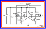
I hope no-one attacks me, I cant help but only be as good as I am, But I cant see how that circuit works, to me the transistors wouldn't shut off because the cap would keep leaking through current and keep the base active, and it never shuts off!

<edit> in the astable multivibrator circuit, those caps must be not be discharging, but i can see they have a loop to, it means theres current constantly going through the cap as its coming out, and it would be going to the transistor base!!! </edit>
 
Last edited:
Top