Sir cards1 . . . . .
firstly i want to add that the lamp has a motion sensor, it has a on/off switch &
i always keep it off, thats why i forgot about it.
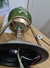
Verify that the ORANGE wired on off switch for the motion sensor is having its slide knob being at the speaker end of its travel, when being left in its
ON position.
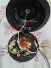
secondly i want to add a more detalied ( de-tailed ! )picture.
That;s being MUCH more helpful . . .as I can now see the battery holder and its (now I know) 3
AA size cells, also verifying its top + RED wire connection and BLACK wire - connection and then their being routed over to the 4 pin WHITE connector as being its pin 3 and 4 connections.
the amount of light of the lamp is fine.
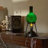
Until I saw WHAT your device was being. I was initially considering illumination. Now we can see its related to creating "effect" lighting .
the batteries are 3 AA 1.5v each.
I just previously acknowledged . . .
Re . . your markups labeling of the (power button), is it being the one that starts up a timed out effects demonstration ?
And its being sealed with a blob upon its WHITE wiring , then going DOWNWARDS , does it make a right angle rotation on the bottom . . . . . to then being forward facing ?
The motion sensor . . . . .
MUCH - MUCH smaller than I am usually encountering . . . .usually they are much larger in diameter.
View attachment 57592
i think the lamp has two LEDs.
Agreed . . . . . one as being the YELLOW flame light illumination and another COLOR one for illumination inside of the separate top flask.
Notice the joined / paired wires YELLOW AND WHITE color coding for that bottom " flame " wiring.
Logical . . . . that the companion GRAY AND WHITE paired cable might be for the separate LED light inside the flask.
CONFIRMATION ? . . . . .
Vewy-vewy cawefully . . . unplug the YELLOW AND WHITE connection and confirm that it no longer lites during an operational sequence.
There is also separate wires of of RED and BLACK, which must be the ultrasonic power drive level for the POWER piezoelectric element responsible for misting / fog inside the top flask. . . . its then wafting upward..
BTW . . . . for my information . . . just how much of that mister /fogging fluid needs to be added and at what intervals ? ? ? ? ?
Cuz' that transducer can be fractured (
KAPUT !) if being left to run unloaded (dry) .
Referring to this blow up link below, of that unit, we can see, what looks like the GRAY AND WHITE PAIR and the RED and BLACK wires get routed . . . . possibly thru 1 hollowed support rod of the 3 and they then end up inside the top flask.
i dont think the 2 yellow wires relate to the mister, i dont know what they are for, check the new picture please.
Right-o . . . agreed . . . . but at THAT time frame, I had not seen the photo of the WHOLE unit and can now see that it would be facing down toward the surface that the whole unit rests upon, with about a 1/4 - 1/2 inch spacing above that surface. . . . . . thereby . . . . letting its sound disperse laterally.
So o o o o o o o o lets let that still be a piezoelectric transducer, but now its acting as a "tweeter" speaker and handling only the very highest of audio frequencies . . . . bat shrieks, etc . . . or exotic high frequency music effects . .
Meanwhile, our other identified speaker is being a "squawker" optimizing on the voice range frequencies sound clips.
With a high likelihood, that the audio driver is being a right and left channel audio power amp, thereby frequency band pass circuitry is passing select high frequencies to the tweeter for one channel and voice frequency ranges get routed to the squawker by the other channel.
You Say . . . .
there is a 3 mm hole underneath it, like a button for a needle? what is it for.
like a button for a needle?
Reword that aspect to be:
That hole size is much like the hole size found in a button . . . . that hole . . . . . which a sewing needle passes through in the sewing on of that button.
what is it for.
The hole is to let the transducers generated sound out, not much area is needed at those high frequencies and limited sound levels.
Not so, on the units squawker speaker.
Now since the WHITE AND GRAY pair as well as the RED AND BLACK individual wires, seem to be non plug terminated . . .possibly hard wired in, beneath the circuit board. Time for you to remove the two Phillips sheet metal screws and provide pics of the other / foil side of the PCB for viewing.
( You're doing
GR E E E E E A T so far ! )
hey, thank you very much for
trying the help!
trying . . . . . . . ¿ trying ?
but . . . . . But . . . . . BUT . . . . .
BUT . . . . . BUT . . . BUT . . . . . BUT . . . . . BUT . . . .
Haven't you received one HELL of a lot more of an
Edd-u-cation after reading my posts, than before arriving here ?
ADD ONS . . .after just having read your 8:33 AM post
Your scent sources liquids, is being puddled on its other side and the whole unit rotates so that that driven disc face, is then facing upward.
This statement was related to the perception of the unit being placed such that the transducer face would be facing upward . . . as explained above . . . it stays facing downward to the surface that the unit is resting upon . . . . . . .so disregard ALL of that earlier statement.
the black & red wires (probably from the mister) that go under the board are connected to the thing you called inductor.
your confirmed observation just nailed that fact !
thus . . . . . leaving the co joined paired set of wires being for flask internal illumination
is what i need to do is to unsolder the mister wires from the inductor (while leaving the inductor?) & remove the speaker plugs & to solder the power wire to the motion detector on off switch?
You describe the unit as needing the prox detector needing to be turned on, if wanted to be activated by your personal proximity
OR ELSE your having pressed the frontal ? manual push button.
It then goes thru its cycle and goes power dead, excepting for the minuscule proximity detector standby power pull . . . . . . all of the LEDS, audio and mister . . . . all power hogs . . . . . are then being disconnected . . . . . . . . until any reactivation.
On each of the two LEDS, one wire is grounded and the other is needing to get +4.5 VDC power from the battery pack via a transistor and current limiting resistor.
The other board side view is needed to see how this happening.
A double pole double throw manual switch is then installed to let the unit operate as it always was, or in its other position as having the proper voltage routed to the LEDS for their constant activation, all of the time that switch is being in that new position. ( The way you wanted it. )
will the electricity amount to the LED's stay the same?
After ascertaining the above info . . . .yeth.
Thaaaaaaaaaaaaaaasit . . . . .
73's de Edd . . . . .
Know what ? . . . . .
My wife is always stealing my t-shirts and sweaters . . . . but . . . . if I were to take just one of her dresses . . . . suddenly its . . . . . . "we need to talk" . . . . . .time.
.


")