This series explores custom PCB art. With our PCBs delivered, it's time to add the additional components!
If you're just joining the fun of PCB art creation, we've done a lot to get to this point! You can see the steps taken by reading previous articles in the series:
We left off the last part of the tutorial with our PCBs ordered from Seeedstudio. Usually, it takes a couple of weeks for custom PCBs to arrive. Once they arrive, the next step is to assemble the PCB. There are three major steps involved in this process:
- Apply solder paste
- Populate the board with components
- Reflow the PCB
Let's go over how to perform each of these steps.
Apply Solder Paste
With the exception of the eInk display, all the components on the Maker Pro robot PCB badge are SMD components. Therefore, we will solder all the components to the board using reflow soldering.
Reflow soldering with SMD components is an extremely useful skill for DIY electronics, so if you’ve never done it before, there are a bunch of good tutorials online about various techniques, like the Reflow Skillet tutorial from SparkFun.
The first step in assembling the PCB is to apply solder paste to the board. This can be done in one of two ways. First, we could use a solder paste stencil. You might have noticed that SeeedStudio Fusion PCB offers stencils to go along with the PCBs they manufacturer. Stencils are very useful for ensuring an even, repeatable solder paste application. Plus using a stencil makes applying solder paste fast and easy.
However, while the solder paste stencil itself is not expensive, only around $10 USD, the size of the stencil makes shipping costs from SeeedStudio much more expensive. So, in this tutorial, I will be using a solder paste syringe to apply solder paste to the board manually. This is not too difficult since there are no fine-pitch components in the design and the components are relatively spread out on the board.
Simply use a syringe to place a small amount of solder paste onto each pad on the PCB.
Applying Solder Paste Video
Populate the Board
With the solder paste applied, now we need to place all the components on the board using ESD-safe tweezers. One of the downsides to making artistic PCBs is that, often, the silkscreen used to aid in correctly identifying and positioning components is either hidden or, in the case of the Maker Pro robot PCB, removed for aesthetic reasons. Therefore, it is useful to have a part placement diagram to identify where each component belongs.
The part placement diagram.
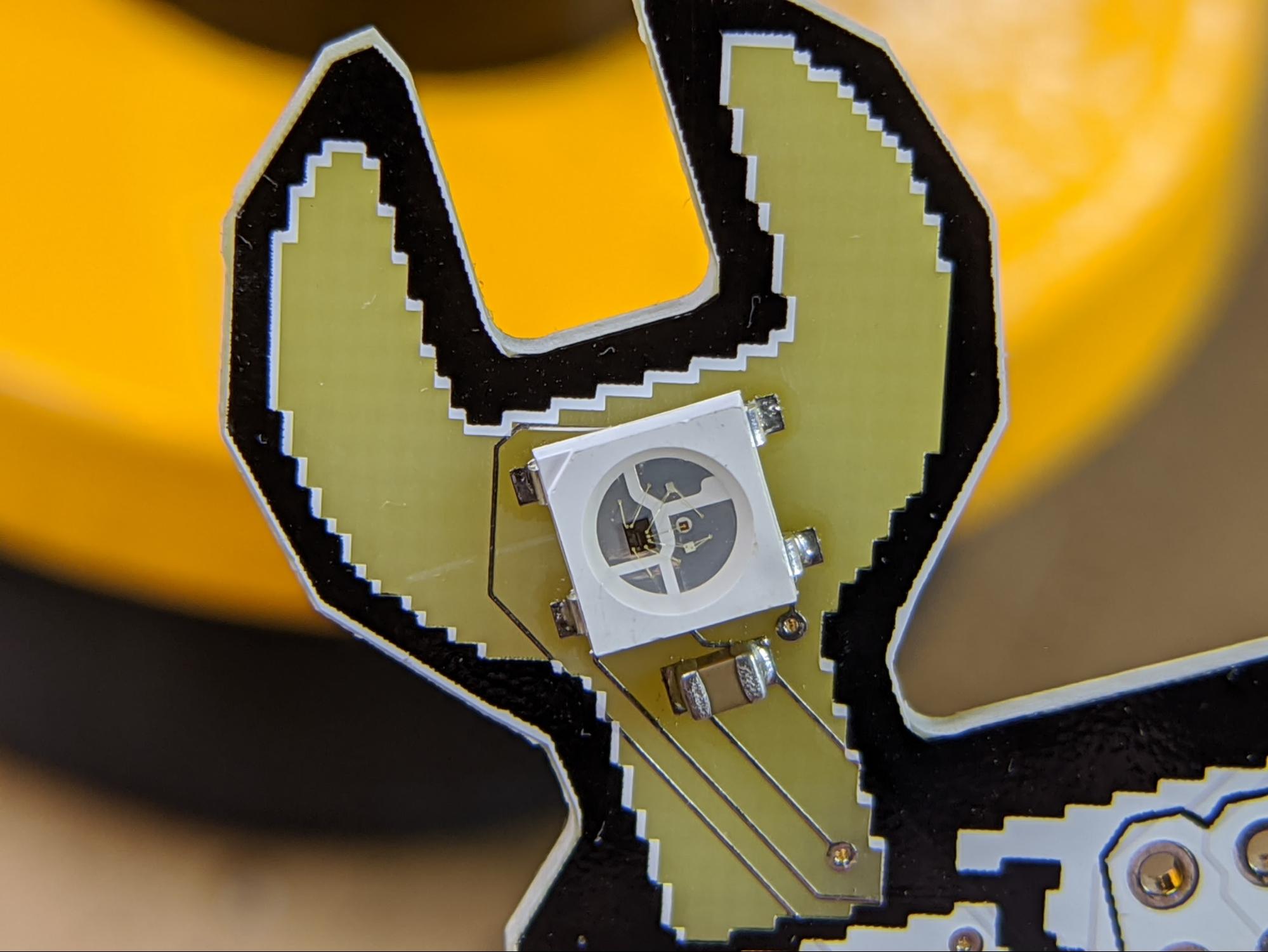
The part placement diagram obviously identifies the values for passive components around the board. It also shows the correct orientation for the RGB LEDs. If you take a close look at the WS2812 RGB LEDs, you will notice that one corner of the PCB is cut off. This corner goes on the side indicated by black bars on the placement diagram.
Here you can see the upper-left corner of the LED is cut out to indicate how to orient the LED on the board.
Carefully place all the components onto the board except for the eInk display and the couple components on the back of the PCB.
Make sure all the components are oriented properly
How to Reflow the PCB
Once you have all the components placed onto the PCB, it is time to reflow the PCB. Reflowing is the process of heating the board until the solder paste melts. When the board cools, permanent solder joints will be made between each component and the pads on the PCB.
There are several methods for reflowing PCBs. Some popular methods include:
- Reflow ovens
- Reflow hotplates
- Hot air reflow machines
- Modified toaster ovens
- Reflow skillets
In this article, I will be using a reflow skillet, in other words, an electric hotplate. A reflow skillet is very inexpensive and it does not require any particular setup. Plus, because it is totally open, you can watch the reflow process. On the other hand, reflow skillets do not have any temperature control, so it can be easier to damage components by getting them too hot. Also, electric hotplates do not heat very evenly.
Anyway, to reflow the Maker Pro robot PCB, simply place the populated PCB onto the hotplate, and set the heat to medium. You will first see the solder paste melt and liquify; it will spread out a bit on the board. Then, the solder flux in the paste will evaporate and emit some fumes. Try not to breath these fumes. Finally, the solder itself will coalesce around the component pins. Once all the solder paste is melted, take the PCB off the hotplate and put it on a heat-proof surface to cool.
Reflow Video
After reflowing the PCB, take a close look at all the components to make sure none moved off the pads or formed solder bridges that could result in short circuits.
Adding the Battery Holder
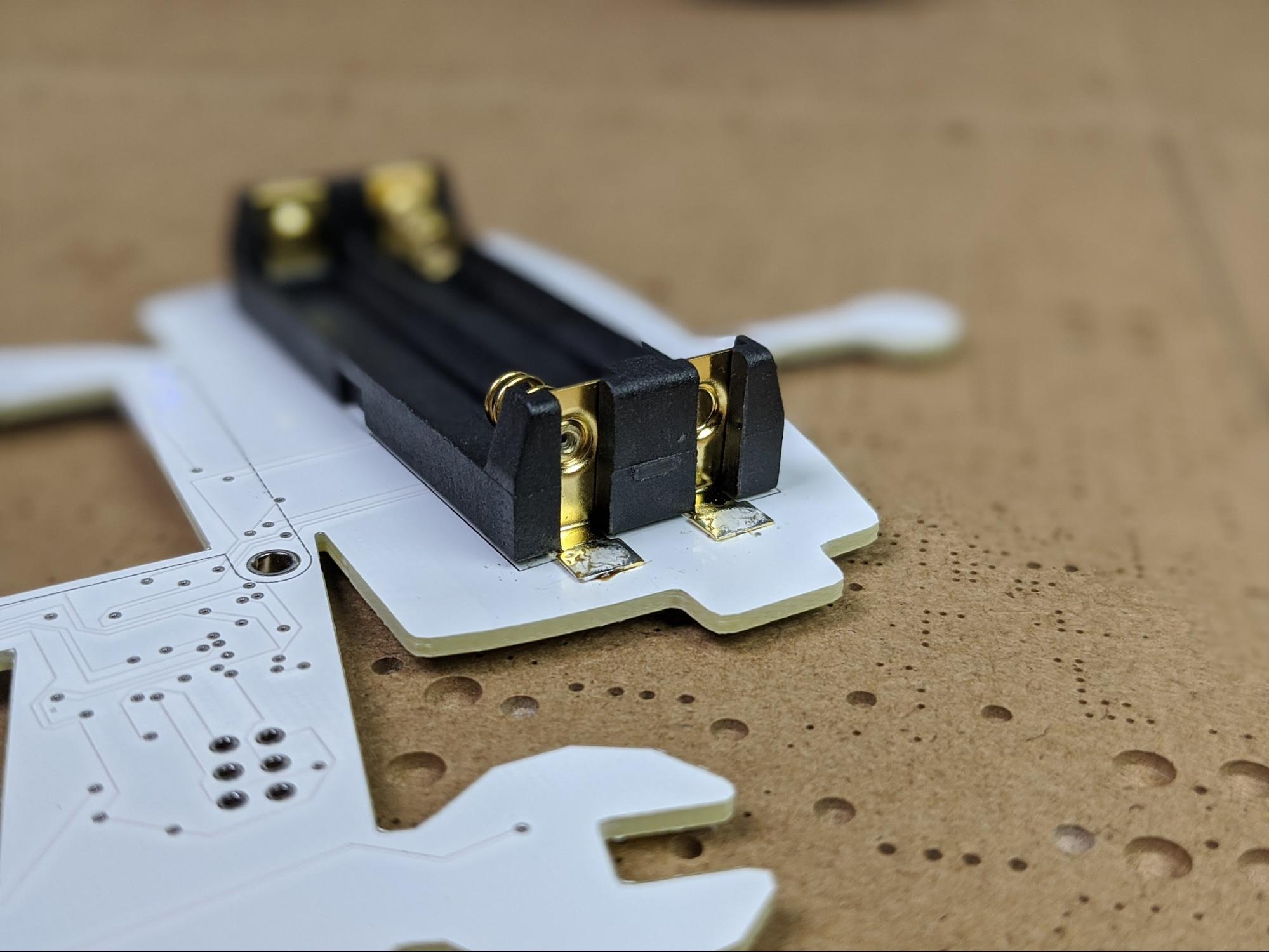
Now that we have everything soldered onto the front side of the PCB (with the exception of the eInk display), we will add the AAA battery holder that goes on the backside of the PCB. This step is quite simple.
The AAA battery holder has four terminals that match four solder pads on the backside of the PCB. First, use a bit of solder to tack one of the terminals to the board. Then, using enough solder to create a complete connection, solder the opposite terminal. With the battery holder firmly held in place, solder the remaining terminals.
Adding the eInk Display
There is only one part left to complete the Maker Pro robot badge assembly, the eInk display module. There are two steps to adding the eInk module to the PCB badge. First, attach a pin header strip to the module and second, solder the module to the PCB. Connect it using nylon spacers.
Solder Headers to the eInk Module
In order to connect the Adafruit eInk module to the Maker Pro robot PCB, we will first need to solder a strip of headers to the display.
The display will mount onto the PCB from the backside. Therefore, we will solder headers to the top of the eInk display module, the same side as the display itself. Orient the pin headers with the longer side protruding from the backside of the PCB. This way, the headers will not stick out too far on the front of the Maker Pro robot badge.
The black plastic part of the headers should be on the front of the eInk module and the long side of the pins should protrude from the back.
With the strip of headers positioned and oriented correctly, simply solder all the headers from the back of the eInk module as you have probably done before with pin headers.
Soldering Pin Headers Video
Having the short side of the headers on the front of the board will prevent the headers from sticking out too far from the front of the PCB badge in an aesthetically-distressing way.
Attach the eInk Module to the PCB Badge
With headers soldered to the eInk display module, we can now mount and connect the module to the robot badge. The module will attach to the PCB using two nylon screws and, of course, the solder joints on the pin headers.
Start by inserting three M2.5 x 10mm nylon screws through the robot PCB from the front to the back through the holes on opposite corners of the central square cutout. Then, place three M2.5 washers onto each screw.
Get the hardware ready to mount the eInk display to the PCB.
Next place the eInk module onto the screws, making certain that the pin headers line up and pass through the line of holes below the square opening on the PCB. Secure the module in place using two M2.5 nylon nuts.
Secure the eInk module using two M2.5 nylon nuts.
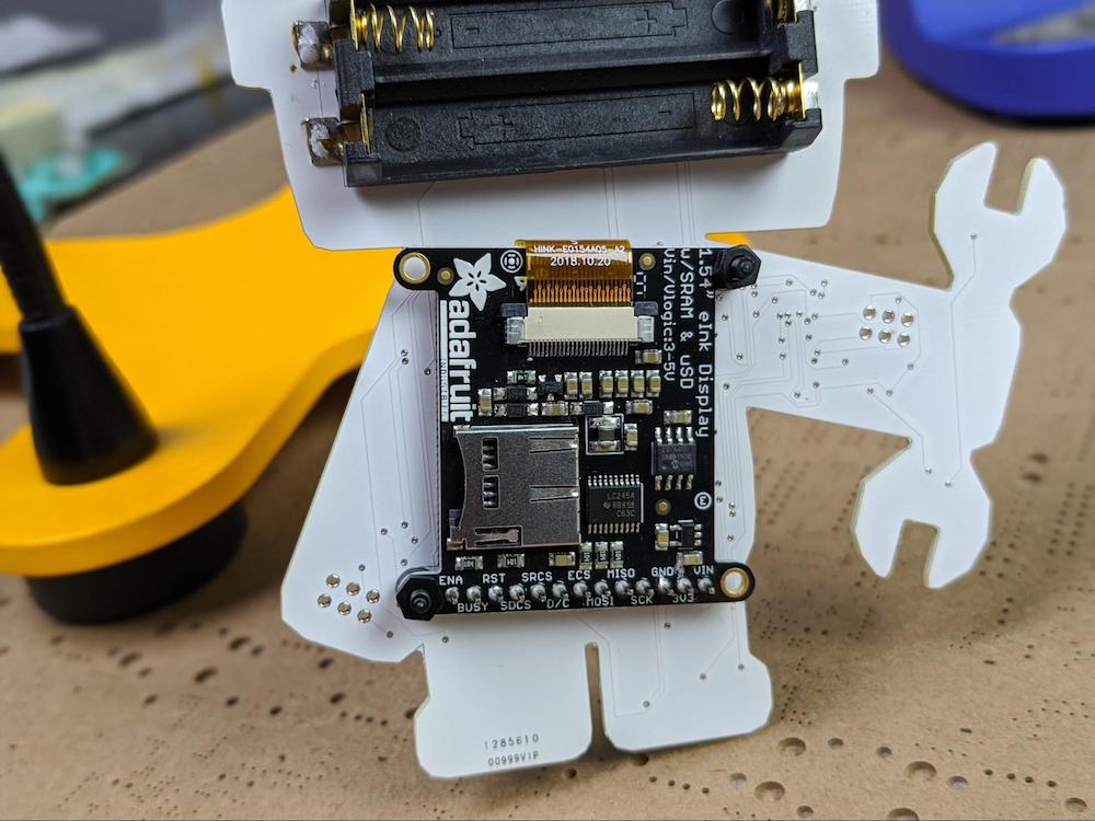
The mounted eInk display from the back.
With the eInk module secured in place, we just need to solder the pin headers that will be protruding out of the front side of the PCB.
Time Lapse Video of Soldering
A front view of the mounted eInk display.
Summary of PCB Assembly and Next Steps
For most of the assembly process for the Maker Pro robot PCB, we used reflow soldering, starting by applying solder paste to all the SMD pads on the PCB, then placing the components themselves, and finally reflowing the board using a reflow skillet. The only part requiring traditional soldering was the eInk display on the robot’s stomach.
With all of that assembly work done, the PCB itself is now complete. The next step is to program the ATmega328 microcontroller with the code necessary to run the hardware.