Maker Pro
Maker Pro

help with IR2110 chips

Alec_t

Jul 7, 2015
3,650
Joined
Jul 7, 2015
Messages
3,650
how many?
A lot more, wth the present design.
If it were me I'd be aiming for a coil with fewer turns, hence less inductance.
The voltage a coil generates is proportional to the number of turns, but the inductance is proportional to the square of the number of turns.
 

Maglatron

Jul 12, 2023
1,655
Joined
Jul 12, 2023
Messages
1,655
so alor, I have remounted both of the coils colser to the magnets ( used a piece of corragated cardboard as a spacer ) now the new arrangement the coil that has always been better at 650 rpm makes 20.91volts AC and the weaker one 15.72volts AC then I wanted to use the resistor to get that other reading for how you found the inductance and it immediately got vey hot so didn't get to make that measurement! but this is progress, thanks! but that is really the best I can do at this point without having a sturdier frame! I have a 150ohm power resistor rated 200watts so I'l be digging that out on the next session!
 
Last edited:

Maglatron

Jul 12, 2023
1,655
Joined
Jul 12, 2023
Messages
1,655
Also when holding the wires onto the meter, I'm getting a little AC tingle which is really promising!
 

Maglatron

Jul 12, 2023
1,655
Joined
Jul 12, 2023
Messages
1,655
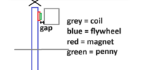
if I dig out the 200watt 15ohm resistor and then use my clamp meter I can also get a current reading I just had a genius ideo too! I'm going to stick 1 pence piece to each magnetto close the gap further
 
Last edited:

Maglatron

Jul 12, 2023
1,655
Joined
Jul 12, 2023
Messages
1,655
so then is it a trade off between voltage and inductance
A lot more, wth the present design.
If it were me I'd be aiming for a coil with fewer turns, hence less inductance.
The voltage a coil generates is proportional to the number of turns, but the inductance is proportional to the square of the number of turns.
 

Maglatron

Jul 12, 2023
1,655
Joined
Jul 12, 2023
Messages
1,655
anyone? I have the penny's ready to stick now!!
 
Last edited:

Alec_t

Jul 7, 2015
3,650
Joined
Jul 7, 2015
Messages
3,650
How are you measuring the AC volts? I ask because general purpose digital multimeters usually give RMS readings assuming the voltage is sinusoidal and fairly low frequency. In your case the waveform is probably not a true sinusoid and the frequency may be higher than the meter was designed for, so there is a question mark over the meter reading if yours is such a meter.
 

Maglatron

Jul 12, 2023
1,655
Joined
Jul 12, 2023
Messages
1,655
there both pretty good! your thoughts? thanks, did you read the bit about the resistor getting very hot?? the second meter says this in the description (Frequency (Hz) 10Hz-1MHz±)
 
Last edited:

Alec_t

Jul 7, 2015
3,650
Joined
Jul 7, 2015
Messages
3,650
Both meters claim to be true rms and the first mentions non-linear loads, so hopefully would give a reasonably accurate voltage measurement.
With 20.9V rms across 100 Ohms the resistor would be dissipating over 4W. Not surprising it got hot!
 

Maglatron

Jul 12, 2023
1,655
Joined
Jul 12, 2023
Messages
1,655
going to lessen the gap even more, with penny's and get the best reading good to know about the true RMS aswell! going to put the 200w resistor 150ohm and take an alternating current reading
 

Alec_t

Jul 7, 2015
3,650
Joined
Jul 7, 2015
Messages
3,650
Putting pennies in the gap will introduce eddy-current losses. No idea how significant they'd be.
 

Maglatron

Jul 12, 2023
1,655
Joined
Jul 12, 2023
Messages
1,655
Will try anyway see if it makes a significant change mind the pun I think it will work rather well, we'll see later on if I get a session to work on the machine!
 
Last edited:

Maglatron

Jul 12, 2023
1,655
Joined
Jul 12, 2023
Messages
1,655
Putting pennies in the gap will introduce eddy-current losses. No idea how significant they'd be.
I disagree the penny's will only further the magnetic field I'm attaching the 1p's to the magnets!!
1707662690433.png
 
Last edited:

Maglatron

Jul 12, 2023
1,655
Joined
Jul 12, 2023
Messages
1,655
Seeing as the voltage doubled when I halved to gap, I'm anxious to see the result after adding in the coins and lowering the distance between the magnets and coils further.1707674324573.png
 
Last edited:

Maglatron

Jul 12, 2023
1,655
Joined
Jul 12, 2023
Messages
1,655
I disagree the penny's will only further the magnetic field I'm attaching the 1p's to the magnets!!
View attachment 62757
because the magnets are not passing the coins, the coins are attached to the magnets! there will however be eddies in the bolt but that is unavoidable with my setup going to try and get 20volts AC from the weaker coil
 

Maglatron

Jul 12, 2023
1,655
Joined
Jul 12, 2023
Messages
1,655
UPDATE:
so glued the pennies to the magnets on the wheel on one side, letting it set and go off overnight!! the magnets were extremely difficult to place, the pennies kept on wanting to go the the middle of the two magnets at a time, took an hour and fingers are all hard fromt the super glue I used (it'll come off over the next couple of days)
 
Last edited:

Maglatron

Jul 12, 2023
1,655
Joined
Jul 12, 2023
Messages
1,655
Lucky you didn't glue yourself to the wheel :)
nearly did, a few times!!! debating weather to stick them the other side as well but a layer of one instead of two (on the side I did, I doubled up to pennies) the gap was a bit larger, it's a gamble though because the gap isn't that big, it would definatly be a good result if it paid off and worst case scenario would be re-mounting a coil! and seeing as it makes 21volts AC at the moments I'm thinking maybe I don't need the extra - but it would be good!! do you have any idea how strong those magnets are? It was a right pain in the neck to mount the first set of pennies but it worked out good.
 
Top